| Topic | Abstract |
|---|---|
| Micro-service Architecture | An overview of the platform architecture |
| Network Model | A representation of the hierarchical network model used to define a scenario and perform emulation |
| Wireless Connectivity | A presentation of the different radio technologies modeled and the connectivity model emulated between the terminal and network nodes. |
| Network Characteristics | A presentation of the different network characteristics that can be defined to control network traffic between a scenario actors |
| Compute Characteristics | A presentation of the different computing characteristics that can be defined to control the behavior of a compute node` |
| Edge Application Architecture | A presentation of various application architectures that can run at the edge |
| Frontend Architecture | A presentation of the AdvantEDGE Frontend architecture |
| NEXT STEP: Platform features |
Micro-service Architecture
AdvantEDGE is a controller software that facilitates deployment of edge applications in a simulated network environment.
It is composed of a collection of micro-services that interact together to allow deployment and testing of edge scenarios.
AdvantEDGE micro-services are packaged in Docker containers which are designed to operate in a Kubernetes environment.
Containers belong to one of 4 groups
| Groups | Description |
|---|---|
| Core-Platform | micro-services implementing the AdvantEDGE controller platform level functionality |
| Core-Sandbox | micro-services implementing the AdvantEDGE controller sandbox level functionality |
| Dependency | 3rd party micro-services upon which the Core micro-services depends |
| Scenario | containers implementing an edge application use case |
High-level overview of AdvantEDGE micro-service architecture:
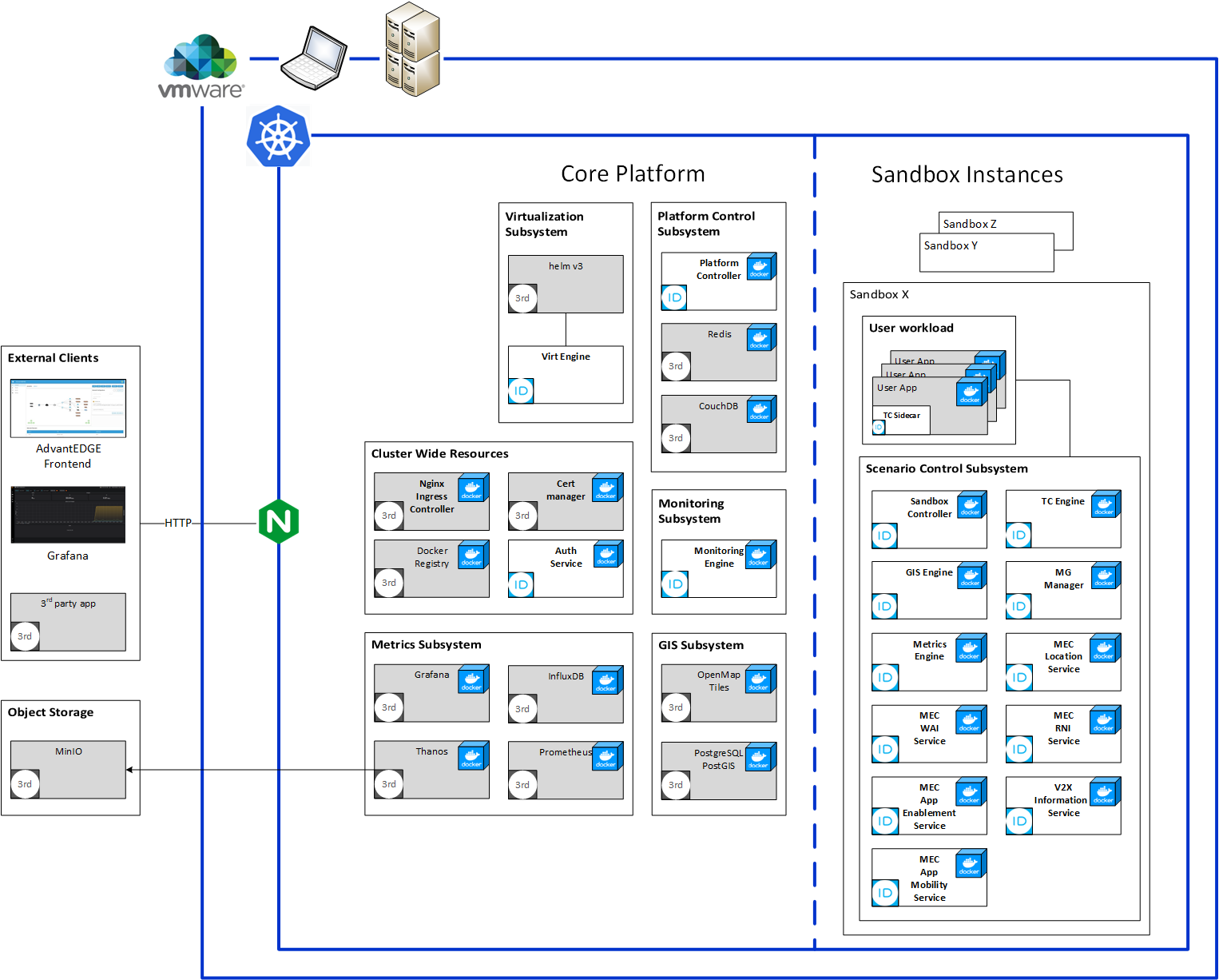
The following subsystems compose the AdvantEDGE Platform:
| Component | Role |
|---|---|
| Platform Subsystem | Control interactions between the user (GUI) and other micro-services (scenario storage & sandbox API) |
| Virtualization Subsystem | Deploy/Delete sandbox & scenario containers |
| Access/Admission Subsystem | L7-HTTP ingress router/docker images storage/K8s admission hooks |
| Monitoring Subsystem | Monitor the state of platform & sandbox containers |
| Metrics Subsystem | Collect & store platform wide metrics |
The following components compose each AdvantEDGE Sandbox:
| Component | Role |
|---|---|
| Sandbox controller | Controls interactions between the user (GUI) and a specific sandbox |
| Traffic Controller Engine | Network characteristic controller for a scenario |
| Traffic Controller Sidecar | Apply location specific network characteristics to a scenario container. Sidecar is dynamically injected into scenario pods at deployment time |
| Mobility Group Manager | Orchestrate edge application state relocation |
| Metrics Engine | Provide an interface to retrieve stored metrics |
| Location Service | Provide an ETSI-MEC compliant Location service API |
| RNI Service | Provide an ETSI-MEC compliant Radio Network Information Service API |
| WAI Service | Provide an ETSI-MEC compliant WLAN Access Information Service API |
| App Enablement Service | Provide an ETSI-MEC compliant Edge Application Enablement Service (App Support API & Service Management API) |
| Application Mobility Service | Povide an ETSI-MEC compliant Application Mobility Service API |
| V2X Information Service | Provide an ETSI-MEC compliant V2X Information Service API |
Network Model
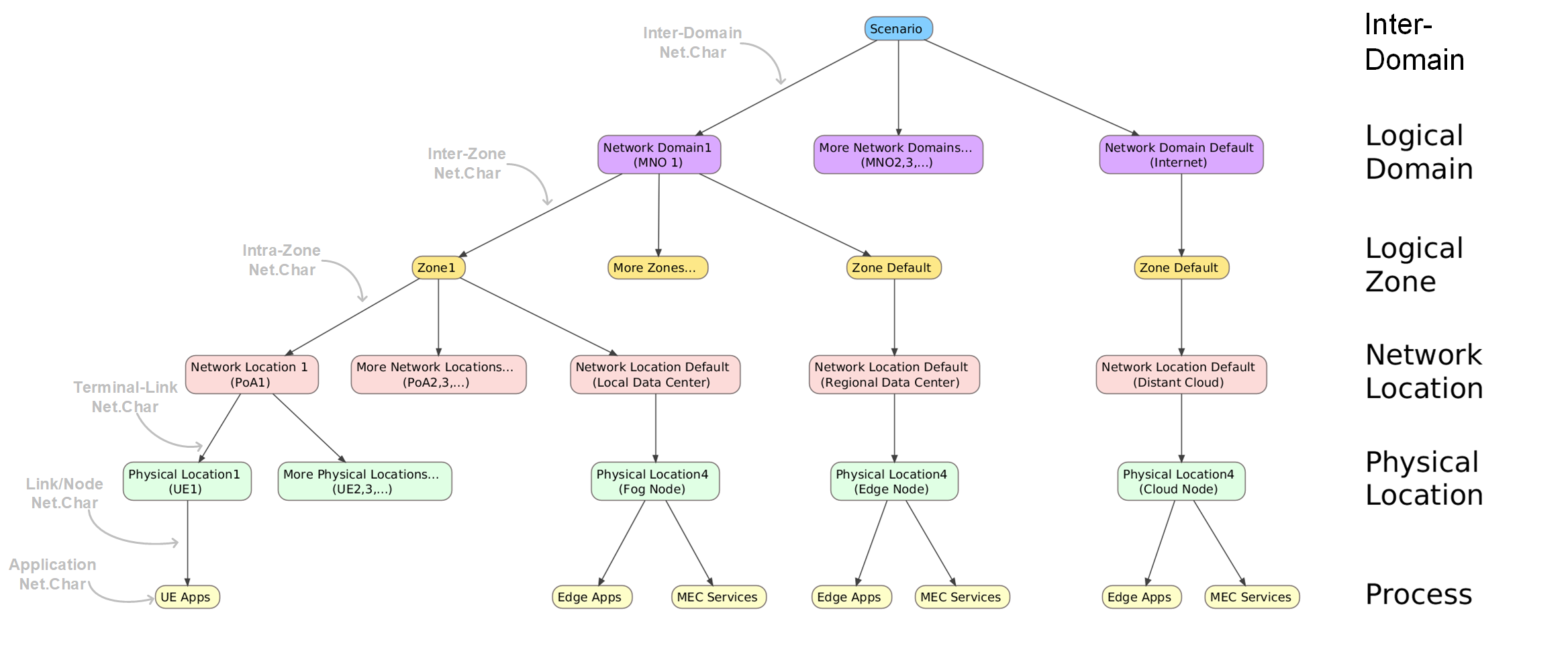
AdvantEDGE uses the following model to define a scenario.
| Layer | Description |
|---|---|
| Scenario | Scenario is the top level component of the network model - AdvantEDGE users creates scenarios - AdvantEDGE can store multiple scenarios - Each scenario is uniquely named - One scenario is deployed at a time (e.g. the “active” scenario) - Scenario defines Inter-Domain network characteristics for traffic crossing between domains |
| Logical Domain | Defines the number and types of domains of within a scenario - Internet/Distant cloud is the default domain - Each MNO represents a domain - Logical Domain defines Inter-Zone network characteristics for traffic crossing between zones |
| Logical Zone | A domain can be decomposed in different zones - Zones allow to group multiple Network locations together - Logical Zone defines Intra-Zone network characteristics for traffic crossing between these network locations |
| Network Location | Defines locations within a zone where nodes attach to the network - Also referred to as a Point of Attachment (PoA) - PoA represent the network connection point of a physical location (e.g. edge/fog/cloud/UE nodes) - Network location defines terminal link network characteristics |
| Physical Location | Defines the physical location of a device; each device in a system occupies its own unique physical location - Defines the node type that occupies the physical location - Example of node types are edge, fog, cloud & UE - All node types can be internal or external to the platform (ex: a physical mobile phone or a physical fog node can be interconnected with the platform scenario) - UEs, edge & fog nodes may dynamically be changed of PoA at scenario runtime by sending a Mobility Event - Physical location defines node network characteristics which represents the node’s impact on traffic (ex. latency/throughput limitations of an overloaded edge node) |
| Process | The “leaf” of the model tree; process represents an application executing at a specific Physical Location - Each process is realized by deploying a pod (container) in K8s - Processes are impacted by network characteristics - External UEs have their process running outside of the AdvantEDGE platform - Process defines application network characteristics which represents application’s impact on traffic (ex. simulate extra latency of a slow disk access / overloaded database) |
Wireless Connectivity
AdvantEDGE supports 4G, 5G and WLAN wireless connectivity types for PoAs within a scenario and a PoA supports a unique technology. Wireless connectivity is reserved for user terminals while edge and cloud nodes are considered wired (e.g. not supporting wireless edge nodes yet)
Accordingly, user terminals can be configured to support a subset or all existing wireless connectivity types. The wireless technologies of a terminal can also be prioritized in case a terminal is in range of several PoAs; in that case a UE would connect via the highest priority wireless technology which is physically the closest to the terminal.
User terminals also support having no connectivity; this can happen if the initial state has been configured as disconnected, if a terminal is out of range of all supported PoAs (when using the GIS automation) or when a user sends a Mobility event to DISCONNECTED destination.
Network Characteristics
AdvantEDGE supports the following network characteristics: latency, jitter, throughput and packet loss.
With regards to the AdvantEDGE model, network characteristics can be applied on a Scenario (Inter-Domains, including Distant cloud elements which are considered as part of another domain), Domains (Inter-Zones), Zones (Intra-Zones), POAs (Terminal-links), Physical Locations (Distant clouds, Edge nodes, Fog nodes, UEs) and Processes (Applications)
At deployment time, containers are started in a Kubernetes pod; AdvantEDGE inserts a companion container (a sidecar) in each deployed pod. The sidecar has the mandate to apply network characteristics from the simulation model. The TC-engine is the micro-service responsible for implementing the real-time simulation model; it constantly maintains & updates network characteristics using multiple inputs such as the scenario values, scenario updates (mobility & net.char events), current bandwidth used by every pod, etc. providing each sidecar of the scenario with values to apply. The “tc” acronym comes from Traffic Control and relates to the underlying tc-netem technology used to realize network characteristics in each sidecar.
About network emulation, the emulation model is path emulation and is only concerned with emulating end-to-end network characteristics between processes, using a network hierarchy defined by the scenario. The resulting network characteristics applied between two communicating processes are then the result of calculations based on the scenario topology (see table below for the details). Internally, each possible path between processes is sub-divided in segments onto which network characteristics are applied; finally, using these segments, an end-to-end path calculation is done. For example, in its simplest form, end-to-end segment latencies are added to compute the path latency; at a higher complexity level, available bandwidth requires a calculation that is function of the segments configuration and real-time consumption by other processes sharing the path segments.
Each network characteristic has the same configuration points: Inter-Domain, Inter-Zone, Intra-Zone, Terminal Link, Node and Application.
| Characteristic | Description |
|---|---|
| Latency | Amount of time that a packet takes to traverse a network to its final destination - Expressed in milliseconds - Latency experienced is the sum of latencies between the source and destination nodes of all the latencies among the path segments between both NOTE: Latency is applied to every packet crossing the network regardless of direction; for example, each packet of the TCP Three-Way Handshake is equally affected when establishing a TCP connection (e.g. a total latency of 10ms between 2 nodes = 30ms TCP session establishment time) |
| Jitter | Variation of the latency parameter - Expressed in milliseconds - Each latency in the model has its own jitter value - Jitter experienced is the sum of jitters between the source and destination node of all the jitters among the path segments between both |
| Jitter Distribution | Distribution model for jitter: supports normal, pareto, pareto-normal or uniform - note distribution is specified at the scenario level and is the same for all nodes in the scenario. |
| Throughput UL/DL | Maximum amount of data moved between two points in the network per direction (UpLink/DownLink) - note: supports asymmetric links - Expressed in Megabits per seconds (Mbps) - Throughput experienced between two processes equals the minimum throughput observed on all the segments that are part of the data path |
| Packet Loss | Packet loss occurs when data packets travelling across the network fail to reach their destination - Expressed as a percentage - Packet Loss experienced between two nodes equals the compounded packet loss observed on the various elements of the data path (e.g, 90% packet loss on a terminal link and 90% packet loss on a fog node would result in a packet loss of 99% (90% for the terminal link packet loss + 90% of the 10% packets that passed the terminal link) |
Path example
A path is a collection of segments with each segments having its own network characteristics.
Two processes exchanging data in one direction is called a flow. A flow contains a path. A path is unidirectional.
The following provides a general overview of a path-segments evaluation between processes executing in different physical locations for a given scenario. 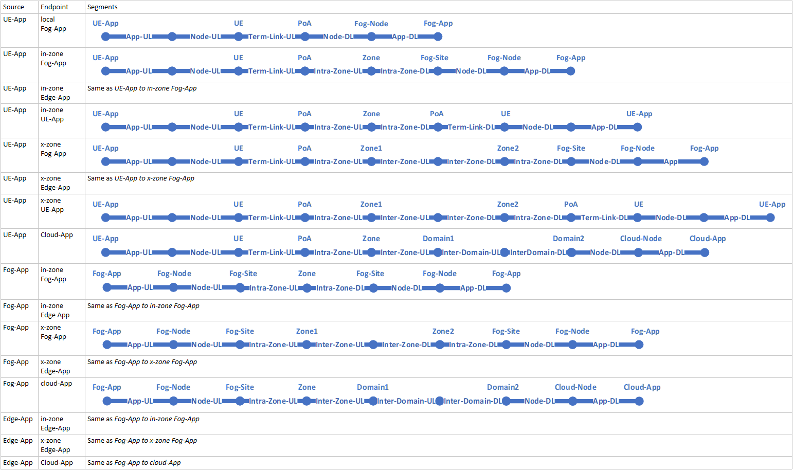
Compute Characteristics
AdvantEDGE supports the following compute characteristics: CPU limits (min & max), memory limits (min & max).
These can be specified at scenario configuration time and cannot be dynamically updated once a scenario is deployed. The compute characteristics are handled by the K8s platform.
CPU limitation will reserve the minimum value and automatically cap CPU usage to the to the maximum value specified. CPU units can be specified as a fraction ( ex: 1.3, 0.5, 0.25 etc.); 1 CPU corresponds to 1 Core, 1 vCPU or 1 Hyperthread depending on the host platform you are running on.
Memory limitation will reserve the minimum value and automatically cap memory usage to the to the maximum value specified. Memory units are in MegaBytes.
A workload will not execute if the system does not have enough resources to satisfy requirements; the following rules apply:
| Min Specified | Max Specified | Description |
|---|---|---|
| Yes | Yes | Both values are used as specified |
| Yes | No | Min is used and the container has no limits |
| No | Yes | Max is used & Min equals Max |
| No | No | No limits from available shared resources |
Edge Application Architecture
Edge applications architecture may be influenced by different deployment, behavioral and grouping models. Below, we provide architectural considerations for developing your edge applciations.
Deployment Model
Edge application deployment model relates to the UE to edge application relationship
Below are a few deployment model examples:
Model 1: One edge application instance serving one UE (one-to-one relationship)
- multiple edge application instances can reside on the same physical node simultaneously Model 2: One edge application instance serving all UEs connected to a PoA (one to many relationship)
- one edge application instance resides on a physical node serving a localized geographical area Model 3: One edge application instance serving all UEs present in a Zone (one-to-many relationship)
- one edge application instance resides on a centrally located node serving a larger geographic area Other edge application deployment models may be valid too!
What if your deployment model is not listed?
AdvantEDGE has been developed to provide as much flexibility as possible, so it may already support other deployment models not listed above out of the box.
If your use case requires a deployment model that is not currently supported, AdvantEDGE can be extended to support it.
Behavioral Model
The behavioral model of an edge application can vary greatly depending on its function, deployment model and overall design.
Below are some considerations that influence the behavioral model of an edge application:
Bootstrapping
- When is the edge application instantiated? - Does it follow an Always-available vs Just-in-time instantiation model? - Where is the application bootstrapped? State Management
- Is the edge application stateful or stateless? - Where do stateful applications get the inital UE state? - Does the state need to be persisted or transfered when UE moves away? UE Mobility
- How does the edge application react to UE mobility events? - Should edge application instance follow UE movement through the network? - Should UE state be transferred to another instance when the UE moves through the network? - Does the MEC platform provide an instance/state transfer service or does it happen at the application level (e.g. "over-the-top")
To help application developers & researchers with edge application design, AdvantEDGE allows to experiment with different models in an agile manner before any deployment happens on the real infrastructure.
Grouping models
AdvantEDGE uses the single-edge application terminology to designate an independent application that execute in a single edge location. Many instances of a single-edge application may be executed on the platform; these applications are not inter-related from the platform point of view and are considered as different applications.
AdvantEDGE uses the multi-edge application terminology to designate an edge application formed by a group of edge applications; the group has multiple instances running on different geographically dispersed nodes. The group is considered as a single application by the platform.
From a UE point of view, accessing a single/multi-edge application at run-time makes no difference; the fact that the application has multiple instances is not known to the UE.
From a network point of view however, a UE accessing a single-edge application consist in routing the traffic to that specific application instance while a UE accessing a multi-edge application consists in routing the traffic to the edge application instance closest to the UE; it is therefore up to the network to route the UE traffic to the closest edge application instance based on the UE location.
AdvantEDGE defines a multi-edge application as an edge application belonging to an edge-group; edge applications with no edge-group are considered as single-edge applications.
In order to provide support to multi-edge applications scenarios, AdvantEDGE implements the application state transfer edge service.
Frontend Architecture
This section provides a bird’s eye view of the AdvantEDGE frontend architecture. This high-level overview should give the reader enough insight into the design choices to get started exploring and augmenting it.
The frontend is based on React and Redux javascript technologies
The frontend is composed of 5 main tabs or pages.
| Tab | Functionality |
|---|---|
| Home | - Platform description - Useful information links |
| Config | - Scenario creation - Updating a scenario - Exporting - Importing a scenario |
| Execution | - Scenario deployment - Events generation - Dashboard observation |
| Monitor | - Dashboard observation - Dashboard customization |
| Settings | - General platform settings |
States
A key portion of the React application state structure is shown below:
{
  ui: {
    page: ...,
    eventCreationMode: true | false,
    currentEventType: MOBILITY_EVENT | NETWORK_CHARACTERISICS_EVENT,
    devMode: true | false,
    automaticRefresh: true | false,
    refreshInterval: <in ms>,
    execShowApps: true | false
    ...
  },
  cfg: {
    type: {...},
    state: {...}
    scenario: {...}
    vis: {...}
    table: {...}
    elementConfiguration: {...}
    apiResults: {...}
    ...
  },
  exec: {
    type: {...}
    state: {...}
    scenario: {...}
    vis: {...}
    table: {...}
    selectedScenarioElement: {...}
    apiResults: {...}
    ...
  },
  settings: {
    ...
  },
}
The following table describes information elements of ui state.
| Path | Description |
|---|---|
ui.page | The current selected page (cfg, exec, etc.) |
ui.eventCreationMode | Says whether the creation pane is open |
ui.automaticRefresh | If true the scenario is refreshed periodically |
ui.refreshInterval | Interval at which the scenario is refreshed. Min is 500 ms |
ui.execShowApps | If apps are shown or not in the network visualization of the exec page |
The following table describes information elements of cfg state.
| Path | Description |
|---|---|
cfg.state | Whether a scenario is opened or not |
cfg.scenario | The currently opened scenario in the config page |
cfg.vis | The data needed for the network visualization on the config page |
cfg.table | The data structure representing the working copy of the loaded scenario |
cfg.elementConfiguration.configuredElement | The network element currently being worked on (creation, update etc.) |
cfg.apiResults | Results of some api calls. i.e. available scenario to load etc. |
The following table describes information elements of exec state.
| Path | Description |
|---|---|
exec.state | Says whether a scenarion is deployed or if the system is idle i.e. no scenario currently deployed |
exec.scenario | The scenario that is currently deployed i.e. ‘active’ |
exec.vis | The data needed for the network visualization on the execution page |
exec.table | The data structure representing the workable copy of the deployed scenario |
exec.selectedElement | The currently selected network element in the deployed scenario along with it’s network characteristics |
exec.apiResults | Results of some api calls |
Reducers
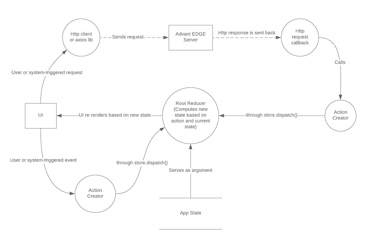
AdvantEDGE frontend uses a Redux reducer; it takes as its arguments an action and the current state of the application and computes a new state for the application. In turn, the main functionality of React can be seen as a function that takes the state and through a render function outputs corresponding html markup.
In AdvantEDGE frontend, the root reducer is composed from more specialized reducers that individually compute state transistions for the following branches of the state tree: ui, cfg, exec and settings. In turn, cfg and exec are each created by combining lower-level reducers, one for each sub-branch of the state.
Actions
The state of the application is updated through Redux actions when user-initiated events occur or following responses from HTTP requests to the AdvantEDGE server.
The following diagram illustrates this general pattern as used in the AdvantEDGE frontend.
The following table describes actions of the AdvantEDGE application.
| State Path | Action Name | Description |
|---|---|---|
ui.page | CHANGE_CURRENT_PAGE | Will result in the specified page being shown to the user. It can be one of the 4 pages or tabs: cfg, exec, monitor or settings |
ui.currentDialog | UI_CHANGE_CURRENT_DIALOG | This is how, through an action, a modal dialog is shown to the user. Which dialog to show is specified in the payload of the action. |
cfg.elementConfiguration.configuredElement | CFG_ELEM_NEW | Triggered when the user wants to add a new element to the scenario being worked on. |
cfg.elementConfiguration.configuredElement | CFG_ELEM_UPDATE | Triggered when the user wants to update an element in the scenario being worked on. |
exec.table | EXEC_CHANGE_TABLE | When triggered, the data representing the working copy of the deployed scenario is modified. |
exec.state.corePodsPhases | EXEC_CHANGE_CORE_PODS_PHASES | Triggered periodically as the state of core pods is polled from the server. This affects the system status led at the top right corner of the app frontend. |
Next Step
Learn about the various Platform features that enable a rich experimentation environment:
- Event generation
- Geospatial Information System (GIS)
- Sandbox environment
- External nodes
- etc.