Feature Overview
AdvantEDGE provides a built-in Geospatial Information System (GIS) that integrates with scenarios.
This feature provides the following capabilities:
- Geospatial characteristics
- Coordinates: devices (UE), point-of-access (PoA) & compute nodes (fog, edge, cloud)
- Wireless signal range limits: PoAs
- Path/speed/end-of-path (EOP) actions: UEs
- Wireless type support & priorities: UEs
- Geospatial measurements
- Distance & signal strength calculations
- Measurements caching
- Map interactions
- Configuration & visualization of geospatial characteristics
- Observation of geospatial assets on map at runtime
- Geospatial Automations
- Mobility events: UE connects to PoA according to PoA Selection algorithm
- UE movement: UE follows defined path according to speed & EOP action
- PoA in-range events: generates event listing all PoA in range
- Network Characteristic update events: drive network characteristics based on distance from PoA (v1.6+)
- Provides a more complete emulation for Location, RNI & WAI services
Micro-Services
- Map server: Open Map Tiles is used to serve map data required by the frontend
- GIS Engine: Implements the GIS REST API
- Databases:
- Postgres/Postgis backend database to store geospatial assets & perform calculations
- Redis backend database to cache geospatial measurements
Scenario Configuration
| Element | Description |
|---|---|
| Device coordinates | Terminal (UE), point-of-access (PoA) & compute nodes (fog, edge, cloud) can be configured in the scenario and geolocated on the map |
| Wireless signal limits | Signal radius of PoAs can be configured in the scenario |
| Terminal movement | It is possible to define a path for terminals and configure the terminal’s speed and end-of-path (EOP) behavior |
| Zone color coding | Zones can be assigned a color so that all PoAs belonging to a zone can easily be recognized on the map |
| Map interactions | To facilitate configuration, geolocation of objects and path definitions are performed by interacting with the map |
Scenario Runtime
| GIS Runtime | Description |
|---|---|
| Runtime map | Real-time observation of geospatial assets position while a scenario is executing |
| Mobility events Automation | Mobility events are automated based on terminal position and available wireless signal; terminal connects to the closest supported PoA in range and supports disconnection event when no suitable wireless signal is available |
| UE movement automation | Terminals follow configured path according to speed & EOP behavior configured; terminals can be paused if desired |
| PoA in-range events | Application state transfer requires to know PoAs in range of the UE; these events can be automatically generated as the UE moves throught he network |
| Net.char events automation | A terminal’s throughput is influenced by its signal strength; network characteristics can therefore be automated using distance to PoA of the terminal |
| Measurements caching | Geospatial measurements are calculated periodically and cached for quick access |
| ETSI MEC Services | Some ETSI MEC services have geospatial component which is now integrated with GIS to provide accurate emulation |
Using GIS feature
Map Provisioning
AdvantEDGE provides an integrated GIS service but does not provide any Map data out of the box. Prior to using the feature, it is therefore necessary to download the desired vector/raster map tiles that you will need for your experiment. These can be downloaded from Open Map Tiles (we tested with OpenStreetMap Vector Tiles). Most maps have a free version available to experiment but may require a license fee for newer versions or to use in other contexts.
NOTE: The Planet map file represent ~60GB of data, we therefore recommend to use only the region for which you are experimenting.
Once the map .mbtiles file is downloaded, copy it in the following location <your-installation-folder>/.meep/omt
NOTE: Only a single .mbtiles file is supported at once.
Scenario Configuration
To use the capabilities offered by GIS, it is necessary to configure geospatial information in the scenario, either by updating an existing scenario or creating a new scenario from scratch.
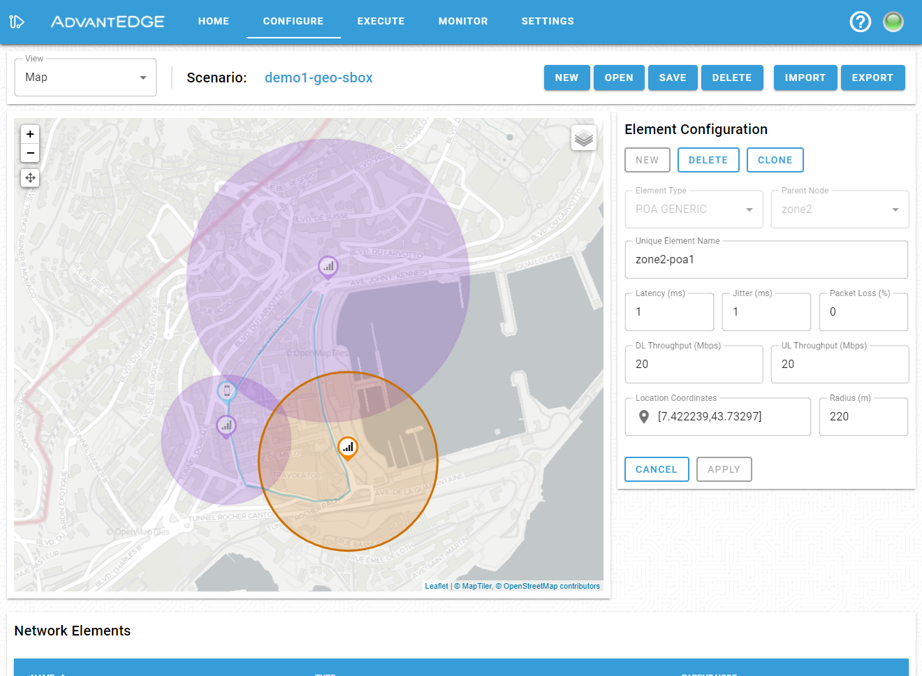
As shown below, the configuration pane enables toggling of the visualization between the network hierarchy and map views (top left corner). Both views may be used to select and configure or edit geospatial data for the various scenario nodes (UE, PoA, edge, fog, cloud).
The map view is used to interactively place elements on the map, change existing element positions and define or modify paths for moving assets such as a UE.
The configuration pane is used to set other data such as PoA signal radius, speed, EOP action or UE supported wireless types.
NOTE: When interacting with the map to configure geospatial data or any other configuration field, it is necessary to hit the APPLY button to retain modifications.
Once the model has been updated, save it in the scenario store.
Scenario Execution
At deployment time, a scenario containing geospatial data will automatically populate the GIS Engine databases.
From the execution tab, it is possible to visualize assets on a map by selecting the map view from the dashboard menu.
More details about a specific asset can be obtained by clicking on it in the map; this provides the latest available asset information.
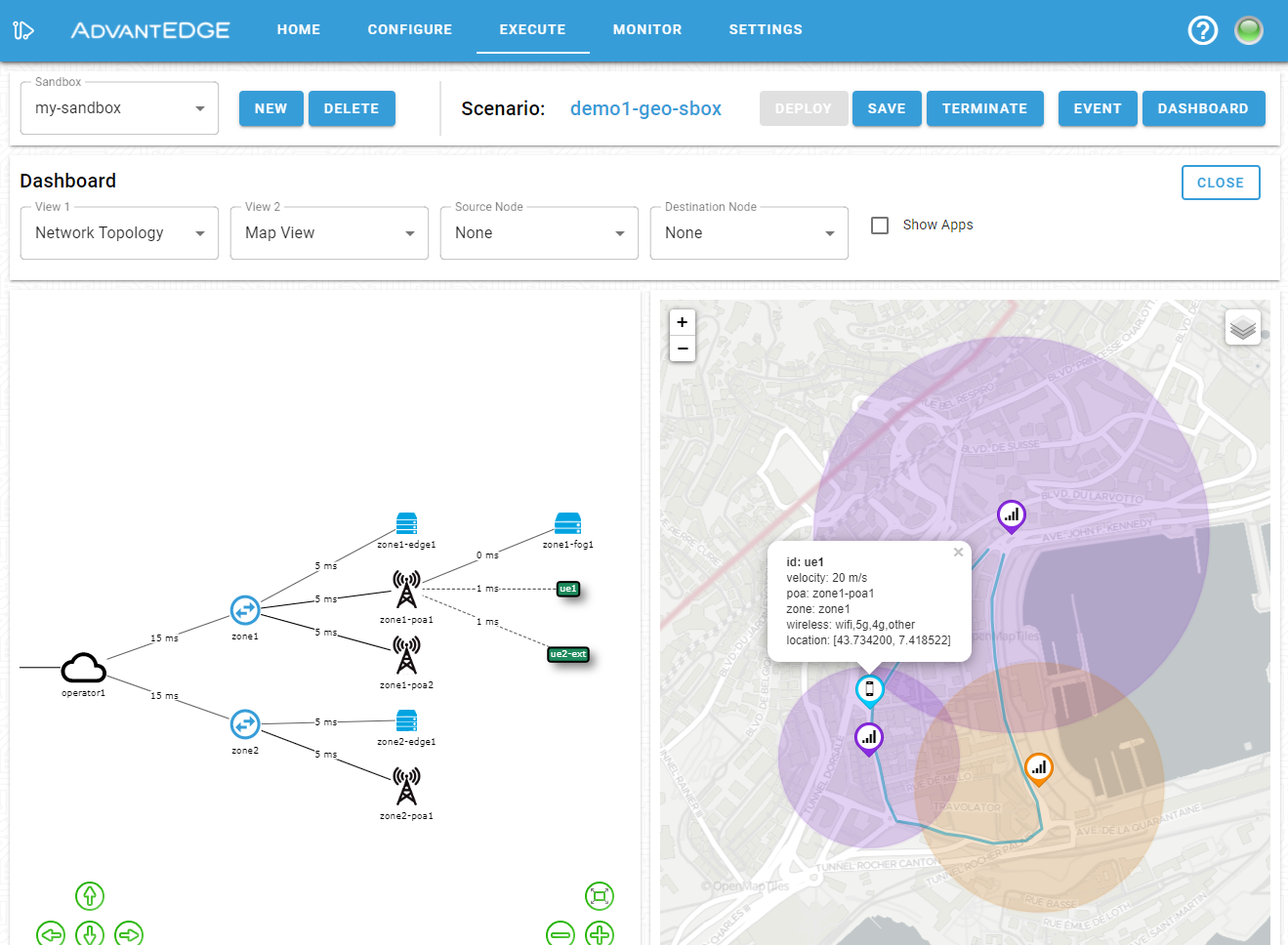
Once the scenario is successfully deployed, the GIS Engine will refresh the location of the various assets according to scenario evolution.
Automations
If everything is static on the map, you may need to enable one or more automation mode; this is done by opening the event menu and selecting automation as shown below.
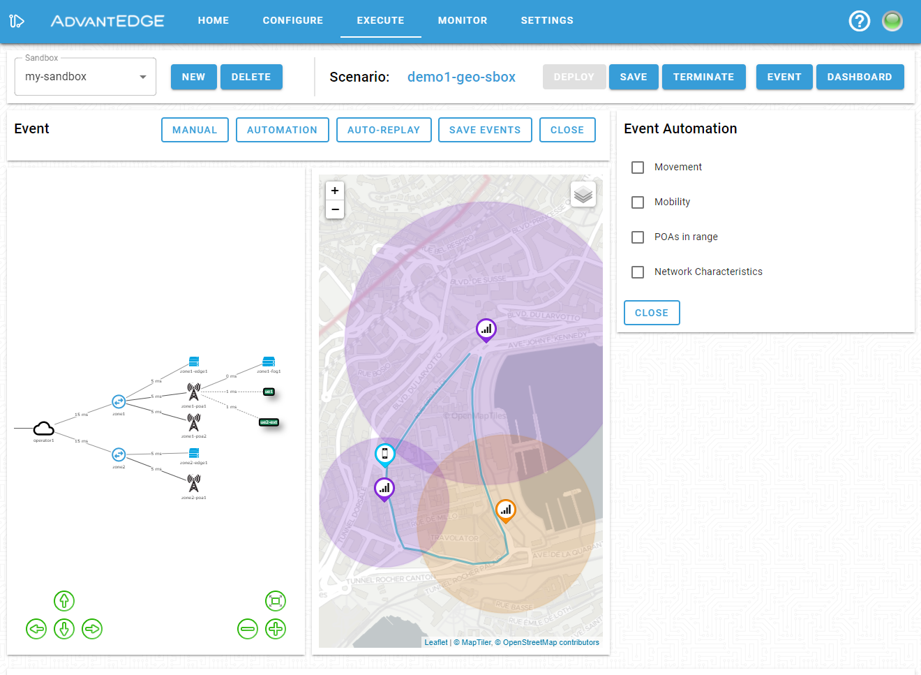
The following automations are supported:
- Movement - toggles UE movement according to their respective paths
- Updates UE position along its path every 1 second
- Runs PoA Selection algorithm and UE measurement calculations after every update (v1.6+)
- Mobility - toggles automatic generation of mobility events
- Mobility event sent for each UE when its selected PoA has changed
- UE always connects to the closest PoA, even if out of range (v1.5)
- PoA Selection algorithm (described below) determines which PoA a UE connects to (v1.6+)
- PoA in range - generates the PoA in range events necessary for the state transfer service
- PoA in range event sent for each UE when its list of in-range PoAs has changed
- Network Characteristics - modulates UE network characteristics based on distance from the PoA
- Not supported (v1.5)
- Sends Network Characteristic update events according to the following algorithm (v1.6+):
- PoA ranges are split into 4 concentric steps (linearly proportional to POA distance over radius)
- Determine which PoA range step each UE is currently located in relative to its associated PoA
- Calculate & apply maximum available UE throughput as a fraction of the maximum PoA throughput
- NOTE: Throughput only updated when UE changes POA range step
PoA Selection
The GIS Engine calculates the distance from each UE to every PoA in order to determine if they are in range and to select which PoA a UE must attach to. This information allows the GIS Engine to automate Mobility, PoA in range and Network Characteristic update events when enabled.
To determine which PoA a UE must attach to, the following algorithm is used:
- No PoA in range:
- UE selects no PoA
- Automation:
- Mobility: A DISCONNECTED Mobility event is sent
- PoA in range: PoA list is set to an empty list
- Network Characteristics: Packet loss is set to 100%
- PoA(s) in range:
- UE selects PoA with highest priority wireless type
- If multiple PoAs with highest priority type, closest PoA is chosen
- If already attached to PoA with highest priority type, remains attached until out of range
- Automation:
- Mobility: Selected PoA is set
- PoA in range: PoA list is set to all PoAs in range
- Network Characteristics: Characteristics calculated based on distance from the selected PoA
- UE selects PoA with highest priority wireless type