Exploring PDSCH PT-RS Configurations
This notebook demonstrates how different Phase-Tracking Reference Signal (PT-RS) configurations affect resource-element allocation in a PDSCH transmission.
Starting from a basic two-layer PDSCH configuration, the notebook explores several PT-RS parameters and visualizes their impact on the PDSCH resource grid, including:
PT-RS time density (
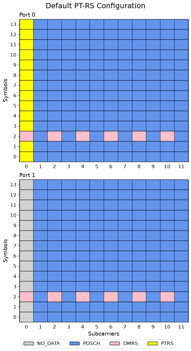
timeDensity)PT-RS frequency density (
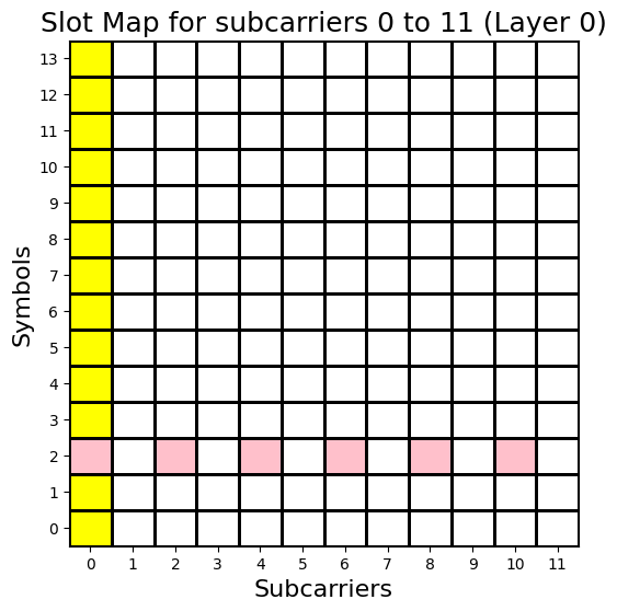
freqDensity)Resource-element offset (
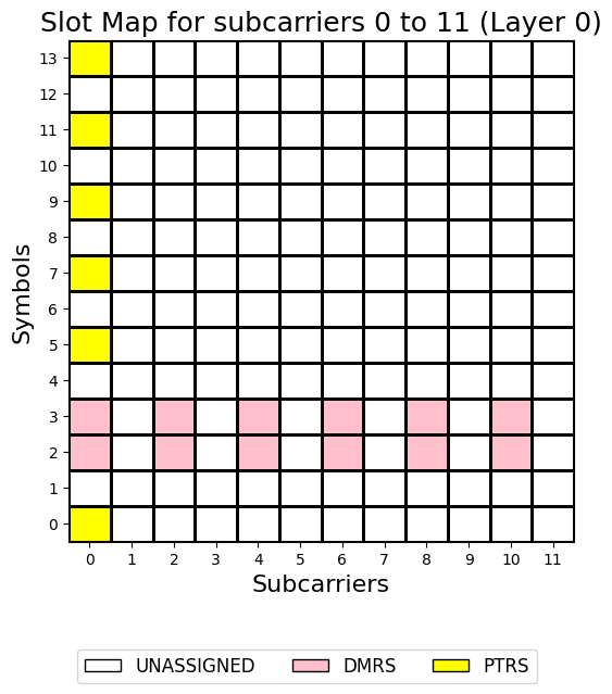
reOffset)Interaction between PT-RS and different DM-RS configurations
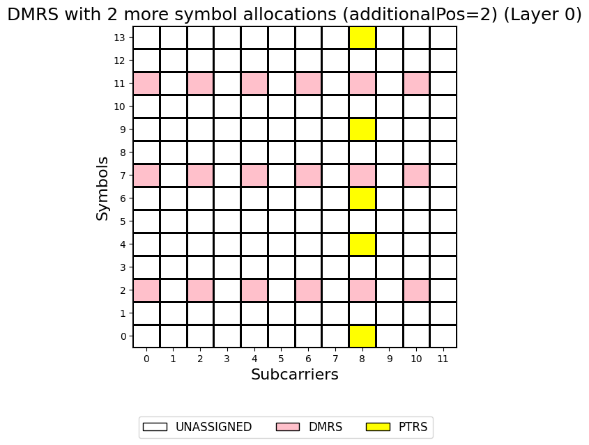
Single-symbol and double-symbol DM-RS
Additional DM-RS symbol positions (
additionalPos)
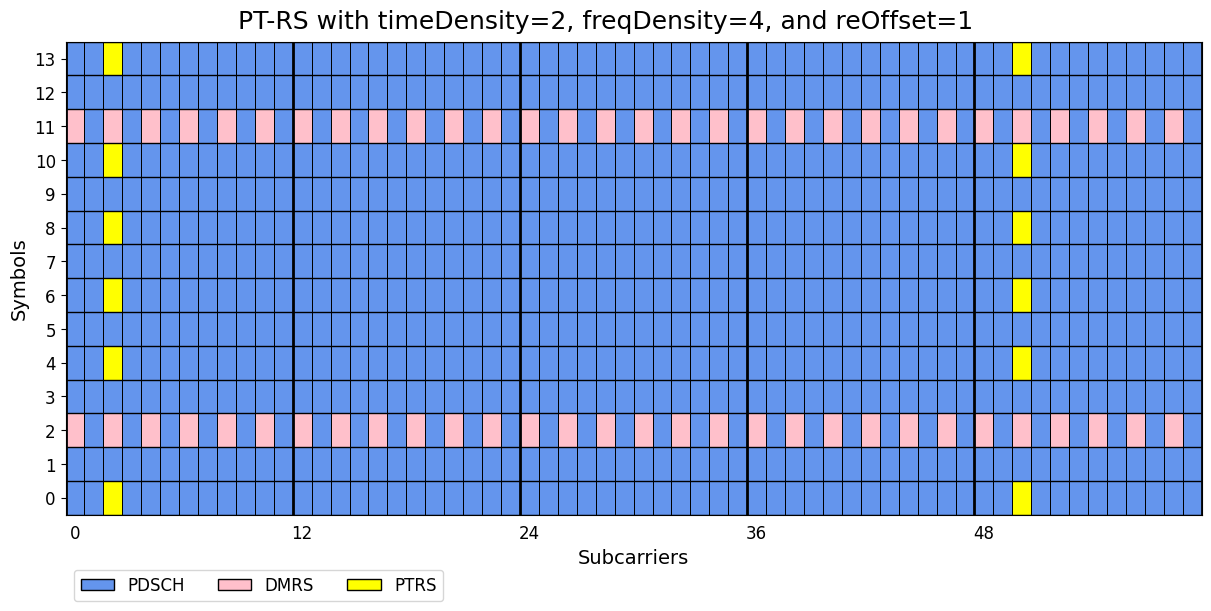
For each configuration, a PDSCH resource grid is generated and displayed, allowing you to examine the placement of PT-RS, DM-RS, and PDSCH data resources. The examples illustrate how PT-RS density changes in both the time and frequency domains, how the PT-RS starting position is controlled by the resource-element offset, and how PT-RS resources coexist with DM-RS allocations.
By comparing the resulting resource maps, you can gain an intuitive understanding of how NeoRadium implements the PT-RS configurations defined by the 5G NR standard and how those configurations influence the resources available for PDSCH data transmission.
[1]:
import numpy as np
import scipy.io

from neoradium import BandwidthPart, PDSCH
[2]:
# Create a bandwidth part with 5 resource blocks and 30 kHz subcarrier spacing
bwp = BandwidthPart(numRbs=5, spacing=30)
bwp.print()
Bandwidth Part Properties:
  Resource Blocks:    5 RBs starting at 0 (60 subcarriers)
  Subcarrier Spacing: 30 kHz
  CP Type:            normal
  Interleaving:       No
  Bandwidth:          1.8 MHz
  symbolsPerSlot:     14
  slotsPerSubFrame:   2
  nFFT:               1024
  frameNo:            0
  slotNo:             0
[3]:
# Create a two-layer PDSCH with mapping type A (default) using all symbols and PRBs in the BWP (default)
pdsch = PDSCH(bwp, numLayers=2)
pdsch.setDMRS()   # Default DM-RS settings
pdsch.setPTRS()   # Default PT-RS settings
pdsch.print()
PDSCH Properties:
  mappingType:               A
  nID:                       1
  rnti:                      1
  numLayers:                 2
  numCodewords:              1
  modulation:                16QAM
  PRG Size:                  Wideband
  portSet:                   0   1
  symSet:                    0   1   2   3   4   5   6   7   8   9   10  11  12  13
  prbSet:                    0   1   2   3   4
  DMRS:
    configType:              1
    nIDs:                    []
    scID:                    0
    sameSeq:                 True
    symbols:                 Single
    typeA1stPos:             2
    additionalPos:           0
    cdmGroups (port:cdm):    0:0  1:0
    deltaShifts (port:cdm):  0:0  1:0
    numCdmGroupsWithoutData: 1
    symSet:                  2
    REs (before shift):      0 2 4 6 8 10
    epreRatioDb:             0 (dB)
  PTRS:
    timeDensity:             1
    freqDensity:             2
    reOffset:                0
    portSet:                 [0]
    epreRatio:               0
    symSet:                  0   1   3   4   5   6   7   8   9  10  11  12  13
[4]:
# Initialize the resource grid of the PDSCH object. This creates an internal Grid object and
# populates it with the DM-RS and PT-RS resource elements
pdsch.initGrid()

# Print summary statistics
print("Number of resource elements:")
stats = pdsch.grid.getStats()
for key, value in stats.items(): print("  %-15s %d"%(key+":", value))

# Draw the grid map for both layers
pdsch.grid.drawMap(pdsch.portSet, title="Default PT-RS Configuration");
Number of resource elements:
  GridSize:       1680
  NO_DATA:        39
  PDSCH:          1542
  DMRS:           60
  PTRS:           39
[5]:
# Show an example with double-symbol DM-RS (symbols=2) with PT-RS timeDensity of 2 which
# means PT-RS resource elements in every other OFDM symbol. (shown for one layer only)
pdsch.setDMRS(symbols=2)
pdsch.setPTRS(timeDensity=2)

# Reinitialize the PDSCH's resource grid since it has new DM-RS configuration
pdsch.initGrid()

# Draw the grid map for the first layer
pdsch.grid.drawMap(title="Double-Symbol DM-RS with PT-RS timeDensity=2");
[6]:
# Use two additional DM-RS symbol positions for DM-RS (additionalPos=2) with PT-RS reOffset=3 (or '11') which
# places PT-RS at RE index 8 (See "resourceElementOffset" in 3GPP TS 38.211, Table 6.4.1.2.2.1-1).
pdsch.setDMRS(additionalPos=2)
pdsch.setPTRS(timeDensity=2, reOffset=3)
pdsch.initGrid()
pdsch.grid.drawMap(title="DM-RS with Two Additional Symbol Positions\nPTRS with timeDensity=2 and reOffset=3");
[7]:
# Comparing freqDensity=2 vs freqDensity=4
# Use one additional DM-RS symbol position for DMRS (additionalPos=1) with PTRS reOffset=1 (or '01') which
# places PT-RS at RE index 2 (See "resourceElementOffset" in 3GPP TS 38.211, Table 6.4.1.2.2.1-1).
# This is shown once with freqDensity=2 and once with freqDensity=4 and compare the map for 5 PRBs
pdsch.setDMRS(additionalPos=1)
pdsch.setPTRS(timeDensity=2, freqDensity=2, reOffset=1)  # PTRS in every other RB
pdsch.initGrid().drawMap(rbRange=(0,4), title="PT-RS with timeDensity=2, freqDensity=2, and reOffset=1")

pdsch.setPTRS(timeDensity=2, freqDensity=4, reOffset=1)  # PTRS in every other 4 RBs
pdsch.initGrid().drawMap(rbRange=(0,4), title="PT-RS with timeDensity=2, freqDensity=4, and reOffset=1");
[ ]: