Channel Models
NeoRadium currently supports two stochastic channel models: Clustered Delay Line (CDL) and Tapped Delay
Line (TDL). These models are implemented as CdlChannel and
TdlChannel classes based on 3GPP TR 38.901. Additionally, NeoRadium provides the
TrjChannel class, which is based on UE trajectories created using ray-tracing
scenarios. The deterministic aspects of the TrjChannel class are primarily derived
from 3GPP TR 38.901 Section 8.4. Furthermore, you can derive your own customized channel models from the
ChannelModel class, as explained below.
Channel Model Base Class
This module serves as the foundation for channel models. Currently, NeoRadium supports three types of channel
models: CDL, TDL, and Trajectory-based channel models. Each model is derived from the ChannelModel
class defined in this module. For more information about these subclasses, please refer to
CdlChannel, TdlChannel,
or TrjChannel.
- class neoradium.channelmodel.ChannelModel(bwp, **kwargs)
This is the base channel model class that handles higher level processing, such as creating Channel Impulse Response (CIR) and channel matrices and applying the channel to a time-domain
Waveformor a frequency-domain resourceGrid.Almost all interactions with channel models are done using the methods of this class. The derived classes mostly implement the lower level processes such as how the channel multipath information is obtained or how MIMO antenna arrays are processed in connection with the channel multipath properties.
- Parameters:
bwp (
BandwidthPart) – The bandwidth part object used by the channel model to create channel matrices.kwargs (dict) –
A set of optional arguments.
- normalizeGains:
A boolean flag. The default value is True, indicating that the path gains are normalized before they are applied to the signals.
- normalizeOutput:
A boolean flag. The default value is True, indicating that the gains are normalized based on the number of receive antennas.
- txDir:
A string that represents the transmission direction, which can be either “Downlink” or “Uplink”. By default, it is set to “Downlink”.
- filterLen:
The length of the channel filter. The default is 16 samples.
- delayQuantSize:
The size of delay fraction quantization for the channel filter. The default is 64.
- stopBandAtten:
The Stop-band attenuation value (in dB) used by the channel filter. The default is 80dB.
- seed:
The seed used by the random functions in the channel model. Setting this to a fixed value ensures that the channel model generates repeatable results. The default value is None, indicating that this channel model uses the NeoRadium’s global random number generator.
- dopplerShift:
The maximum Doppler shift in Hertz. The default value is 40 Hertz, which corresponds to a speed of approximately 10 kilometers per hour. A value of zero makes the channel model static. For trajectory-based channel models, this value is automatically assigned based on the maximum trajectory speed.
- carrierFreq:
The carrier frequency of the channel model in hertz. The default is 3.5 GHz.
Other Properties:
All of the parameters mentioned above are directly available. Here is a list of additional properties:
- coherenceTime:
The Coherence time of the channel model in seconds. This is calculated based on the
dopplerShiftparameter.- sampleRate:
The sample rate used by this channel model. For 3GPP standard, this is set to 30,720,000 samples per second.
- print(indent=0, title=None, getStr=False)
Prints the properties of this channel model object.
- Parameters:
indent (int) – The number of indentation characters.
title (str or None) – If specified, it is used as a title for the printed information. If None (default), the text “Channel Model Properties:” is used for the title.
getStr (Boolean) – If True, returns a text string instead of printing it.
- Returns:
If the
getStrparameter is True, then this function returns the information in a text string. Otherwise, nothing is returned.- Return type:
None or str
- restart(restartRanGen=False, applyToBwp=True)
Resets the state of this channel model to the initial state.
- Parameters:
restartRanGen (Boolean) – If a
seedwas not provided to this channel model, this parameter is ignored. Otherwise, ifrestartRanGenis set to True, the random number generator of this channel model is reset. IfrestartRanGenis False (the default), the random number generator is not reset. This means that ifrestartRanGenis False, for stochastic channel models, calling this function starts a new sequence of channel instances, which differs from the sequence when the channel was instantiated.applyToBwp (Boolean) – If set to True (the default), this function restarts the
BandwidthPartassociated with this channel model. Otherwise, theBandwidthPartstate remains unchanged.
- goNext(applyToBwp=True)
This method is called after each application of the channel to a signal to move to the next slot. It advances the channel model’s internal variable that keeps track of the current time.
- Parameters:
applyToBwp (Boolean) – If set to True (the default), this function advances the timing state of the
BandwidthPartassociated with this channel model. Otherwise, theBandwidthPartstate remains unchanged.
- getMaxDelay()
Calculates and returns the maximum delay of this channel model in time-domain samples for the current slot.
- Returns:
The maximum delay of this channel model in number of time-domain samples for the current slot.
- Return type:
int
- applyToGrid(grid)
This function applies the channel model to the transmitted resource grid object specified by
gridin the frequency domain. It then returns the received resource grid in a newGridobject. The function first calls thegetChannelMatrix()method to obtain the channel matrix. Subsequently, it invokes theapplyChannel()method of theGridclass to calculate the received resource grid.- Parameters:
grid (
Grid) – The transmitted resource grid. AnNt x L x KGridobject, whereNtrepresents the number of transmit antennas,Ldenotes the number of OFDM symbols, andKis the number of subcarriers in the resource grid.- Returns:
A resource grid containing the received signal. An
Nr x L x KGridobject, whereNrrepresents the number of receive antennas,Ldenotes the number of OFDM symbols, andKis the number of subcarriers in the resource grid.- Return type:
- getChannelMatrix()
This method calculates and returns the channel matrix at the current time. The channel matrix is a 4-D complex NumPy array with dimensions
L x K x Nr x Nt, whereLrepresents the number of OFDM symbols,Kdenotes the number of subcarriers,Nris the number of receive antennas, andNtindicates the number of transmit antennas. Please refer to the notebook Channel Matrix for an example of using this function.- Returns:
A 4-D complex NumPy array with dimensions
L x K x Nr x Nt, whereLrepresents the number of OFDM symbols,Kdenotes the number of subcarriers,Nris the number of receive antennas, andNtindicates the number of transmit antennas.- Return type:
4-D complex NumPy array
- applyToSignal(inputSignal)
This method applies the channel model to the time-domain waveform specified by
inputSignaland returns anotherWaveformobject containing the received signal in time domain.- Parameters:
inputSignal (
Waveform) – The transmitted time-domain waveform. AnNt x NsWaveformobject, whereNtrepresents the number of transmit antennas andNsdenotes the number of time samples in the transmitted waveform.- Returns:
A
Waveformobject containing the received signal. It is anNr x NsWaveformobject whereNrdenotes the number of receive antennas andNsrepresents the number of time samples in the received waveform.- Return type:
- getChannelGains()
This function calculates the path gains for the current slot at the beginning of each symbol. The result is a 4-D tensor of shape
L x Nr x Nt x Np, whereLrepresents the number of symbols per slot,NrandNtindicate the number of receiver and transmitter antennas, respectively, andNpdenotes the number of paths. The path gains are normalized based on thenormalizeOutputandnormalizeGainsvalues.- Returns:
The path gains as a NumPy array of shape
L x Nr x Nt x Np.- Return type:
4-D complex NumPy array
- classmethod getEffChannel(channelMatrix, precoder)
This class method can be used to calculate the effective channel based on the given
channelMatrixand theprecoder.- Parameters:
channelMatrix (NumPy array) – An
L x K x Nr x Ntcomplex NumPy array representing the channel matrix, whereLrepresents the number of OFDM symbols,Kdenotes the number of subcarriers,Nris the number of receive antennas, andNtindicates the number of transmit antennas. It can be the actual channel matrix obtained directly from a channel model using thegetChannelMatrix()method (perfect estimation), or an estimated channel matrix obtained using theestimateChannelLS()method.precoder (List of tuples or NumPy array) –
The precoder information can take one of the following forms:
- Wideband:
precoderis anNt x Nlmatrix whereNtis the number of transmitter antennas which must match the number of transmitter antennas in thechannelMatrixabove, andNlis the number of transmission layers. In this case, the sameNt x Nlmatrix is applied to all subcarriers of thechannelMatrix.- Using PRGs:
precoderis a list of tuples of the form (groupRBs,groupF). For each entry in the list, theNt x Nlprecoding matrixgroupFis applied to all subcarriers of the resource blocks listed ingroupRBs. In this case, different precoders are applied to different sub-bands of thechannelMatrix.
You can use the
getPrecodingMatrix()method to obtain a precoder.
- Returns:
The effective channel as an
L x K x Nr x NlNumPy array, whereLrepresents the number of OFDM symbols,Kdenotes the number of subcarriers,Nris the number of receive antennas, andNlindicates the number of transmission layers.- Return type:
4-D complex NumPy array
CDL Channel Model
This module implements the CdlChannel class which encapsulates the functionality of the
Clustered Delay Line (CDL) channel model.
- class neoradium.cdl.CdlChannel(bwp, profile='A', **kwargs)
This class implements the Clustered Delay Line (CDL) channel model based on 3GPP TR 38.901. It is derived from the
ChannelModelclass.All of the API functions used in typical use cases are explained in the documentation of the
ChannelModelclass.The typical use case involves instantiating a
CdlChannelobject and then calling functions such asgetChannelMatrix(),applyToSignal(),applyToGrid(), etc. Please refer to the notebook Channel Matrix for an example of using this class.- Parameters:
bwp (
BandwidthPart) – The bandwidth part object used by the channel model to create channel matrices.profile (str or None) – The CDL profile. It can be one of ‘A’, ‘B’, ‘C’, ‘D’, ‘E’, or None. See 3GPP TR 38.90, Section 7.7.1 for more information. Use None to indicate a customized version of CDL channel (See Customizing CDL Model).
kwargs (dict) –
Here’s a list of additional optional parameters that can be used to further customize this channel model:
- normalizeGains:
A boolean flag. The default value is True, indicating that the path gains are normalized before they are applied to the signals.
- normalizeOutput:
A boolean flag. The default value is True, indicating that the gains are normalized based on the number of receive antennas.
- txDir:
A string that represents the transmission direction, which can be either “Downlink” or “Uplink”. By default, it is set to “Downlink”.
- filterLen:
The length of the channel filter. The default is 16 samples.
- delayQuantSize:
The size of delay fraction quantization for the channel filter. The default is 64.
- stopBandAtten:
The stop-band attenuation (in dB) used by the channel filter. The default is 80 dB.
- seed:
The seed used by the random functions in the channel model. Setting this to a fixed value ensures that the channel model generates repeatable results. The default value is None, indicating that this channel model uses the NeoRadium’s global random generator.
- dopplerShift:
The maximum Doppler shift in Hertz. The default value is 40 Hertz, which corresponds to a speed of approximately 10 kilometers per hour. A value of zero makes the channel model static. For trajectory-based channel models, this value is automatically assigned based on the maximum trajectory speed.
- carrierFreq:
The carrier frequency of the channel model in Hz. The default is 3.5 GHz.
- delaySpread:
The delay spread in nanoseconds. The default is 30 ns. It can also be a string containing one of the values in following table (See 3GPP TR 38.901, table 7.7.3-1)
Delay Spread str
Delay spread
’VeryShort’
10 ns
’Short’
30 ns
’Nominal’
100 ns
’Long’
300 ns
’VeryLong’
1000 ns
- ueDirAZ:
This is a list of two angles for the Azimuth and Zenith of the UE’s direction of movement in degrees. The default value is [0, 90], which indicates movement along the x-axis. In the current version, the base station is assumed to be stationary.
- txAntenna:
The transmitter antenna, which is an instance of
AntennaElement,AntennaPanel, orAntennaArrayclass. If not specified, a single antenna element is automatically created by default.- rxAntenna:
The receiver antenna, which is an instance of
AntennaElement,AntennaPanel, orAntennaArrayclass. If not specified, a single antenna element is automatically created by default.- txOrientation:
The orientation of the transmitter antenna. This is a list of three angle values in degrees: bearing angle (math:alpha), downtilt angle (math:beta), and slant angle (math:gamma). The default orientation is [0,0,0]. For more information, please refer to 3GPP TR 38.901, Section 7.1.3.
- rxOrientation:
The orientation of receiver antenna. This is a list of three angle values in degrees: bearing angle (math:alpha), downtilt angle (math:beta), and slant angle (math:gamma). The default orientation is [180,0,0]. For more information, please refer to 3GPP TR 38.901, Section 7.1.3.
- kFactor:
The K-Factor (in dB) used for scaling. The default is None. If not specified (
kFactor=None), K-factor scaling is disabled.- xPolPower:
The cross-polarization Power in dB. The default is 10 dB. For more details please refer to “Step 3” in 3GPP TR 38.901, Section 7.7.1.
- angleScaling:
The Angle Scaling parameters. If specified, it must be a tuple of 2 NumPy arrays.
The first item specifies the mean values for angle scaling. It’s a 1-D NumPy array containing four values for: the Azimuth angle of Departure, Azimuth angle of Arrival, Zenith angle of Departure, and Zenith angle of Arrival.
The second item specifies the RMS angle spread values. It is a 1-D NumPy array containing four RMS values for: the Azimuth angle of Departure, Azimuth angle of Arrival, Zenith angle of Departure, and Zenith angle of Arrival. For more information, please refer to Angle Scaling below.
If this value is set to None (the default), the Angle Scaling is disabled.
- pathDelays:
Use this parameter to customize or override the default path delays, which are set based on the CDL channel model as defined in 3GPP TR 38.901. In most use cases, you don’t need to specify this parameter. For more information, see Customizing CDL Model below.
- pathPowers:
Use this parameter to customize or override the path power settings, which are set by default based on the CDL channel model as defined in 3GPP TR 38.901. You don’t need to specify this parameter for most use cases. For more information, refer to Customizing CDL Model below.
- aods:
Use this parameter to customize or override the Azimuth angles of Departure, which are set by default based on the CDL channel model as defined in 3GPP TR 38.901. You don’t need to specify this parameter for most use cases. For more information, see Customizing CDL Model below.
- aoas:
Use this parameter to customize or override the Azimuth angles of Arrival, which are set by default based on the CDL channel model as defined in 3GPP TR 38.901. You don’t need to specify this parameter for most use cases. For more information, see Customizing CDL Model below.
- zods:
Use this parameter to customize or override the Zenith angles of Departure, which are set by default based on the CDL channel model as defined in 3GPP TR 38.901. You don’t need to specify this parameter for most use cases. For more information, see Customizing CDL Model below.
- zoas:
Use this parameter to customize or override the Zenith angles of Arrival, which are set by default based on the CDL channel model as defined in 3GPP TR 38.901. You don’t need to specify this parameter for most use cases. For more information, see Customizing CDL Model below.
- angleSpreads:
Use this parameter to customize or override the RMS Angle spread (in degrees) used to normalize angles. This parameter specifies four values corresponding to the Azimuth angle of Departure, Azimuth angle of Arrival, Zenith angle of Departure, and Zenith angle of Arrival. By default, these values are set based on the CDL channel model as defined in 3GPP TR 38.901. You don’t need to specify this parameter for most use cases. For more information, see Customizing CDL Model below.
Please note that this should not be confused with angle spread values used for angle scaling (See
angleScalingabove).- hasLos:
Use this parameter to customize or override the
hasLosproperty of this channel model. By default, this property is set based on the CDL channel model as defined in 3GPP TR 38.901. You don’t need to specify this parameter for most use cases. For more information, see Customizing CDL Model below.- kFactorLos:
Use this parameter when customizing the CDL model. It represents the K-Factor ratio (in dB) for the LOS (Line of Sight) cluster (the first cluster). You don’t need to specify this parameter for most use cases. For more information, refer to Customizing CDL Model below. By default, when customizing the CDL model, this value is set to the difference in path powers (in dB) between the first and second clusters.
Note
All angle values provided to this class are in degrees. However, internally, the class uses radian values for all calculations. Therefore, when you access any of the angle values, such as
aods,aoas,zods, andzoas, remember that they are in radians.Other Properties:
All of the parameters mentioned above are directly available. Here is a list of additional properties:
- coherenceTime:
The Coherence time of the channel model in seconds. This is calculated based on the
dopplerShiftparameter.- sampleRate:
The sample rate used by this channel model. For 3GPP standard, this is set to 30,720,000 samples per second.
- nrNt:
A tuple of the form
(nr,nt), wherenrandntare the number of receiver and transmitter antennas elements correspondingly.- rayCoupling:
This property is used internally for ray coupling. See Step 2 in 3GPP TR 38.901, Section 7.7.1 for more details.
- initialPhases:
The random initial phases used when creating channel gains. See Step 10 in 3GPP TR 38.901, Section 7.5 for more details.
Angle Scaling:
If
angleScalingis set to None, angle scaling is disabled. Otherwise, it is applied to all angles of arrival and departure for all clusters, as per 3GPP TR 38.901, Section 7.7.5.1 and Annex A.Customizing CDL Model:
There are two different ways to customize the CDL model:
You can select one of the predefined CDL profiles (A, B, C, D, or E) and then modify the model’s parameters by providing additional information. For instance, you can choose the CDL-B model and override the standard path delays by specifying your own path delays.
You can also create your own model entirely from scratch. Initially, pass None for the
profileparameter and then specify all the channel model parameters. Please note that in this case, you must specify at least the following parameters:pathDelays
pathPowers
aods
aoas
zods
zoas
hasLos
You can also optionally specify the following values:
angleSpreads (defaults to [4.0, 10.0, 2.0, 2.0] if not specified)
kFactorLos (defaults to
pathPowers[0]-pathPowers[1])
Also note that if your channel model contains a LOS cluster, it must be the first cluster in the lists, and the
hasLosparameter should be set to True.
- print(indent=0, title=None, getStr=False)
Prints the properties of this CDL channel model object.
- Parameters:
indent (int) – The number of indentation characters.
title (str or None) – If specified, it serves as the title for the printed information. If None (the default), an automatic title is generated based on the channel model parameters.
getStr (Boolean) – If True, returns a text string instead of printing it.
- Returns:
If the
getStrparameter is True, then this function returns the information in a text string. Otherwise, nothing is returned.- Return type:
None or str
- restart(restartRanGen=False, applyToBwp=True)
This method first re-initializes the random object if a
seedwas provided to this channel model and therestartRanGenparameter is set to True. It then randomly re-initializes the ray coupling and initial phases and calls the base classrestart().- Parameters:
restartRanGen (Boolean) – If a
seedwas not provided to this channel model, this parameter is ignored. Otherwise, ifrestartRanGenis set to True, this channel model’s random generator is reset and ifrestartRanGenis False (default), the random generator is not reset. This means ifrestartRanGenis False, calling this function starts a new sequence of channel instances, which differs from the sequence when the channel was instantiated.applyToBwp (Boolean) – If set to True (the default), this function restarts the
BandwidthPartassociated with this channel model. Otherwise, theBandwidthPartstate remains unchanged.
- classmethod getChanGen(numChannels, bwp, profiles='ABCDE', delaySpread=(10, 500), ueSpeed=(10, 70), ueDir=(0, 360), **kwargs)
Returns a generator object that can generate CDL channel matrices based on the given parameters and criteria.
Refer to the notebook Creating random CDL channels for a dataset for an example of using this method.
- Parameters:
numChannels (int) – The number of channel matrices generated by the returned generator.
bwp (
BandwidthPart) – The bandwidth part object used by the returned generator to construct channel matrices.profiles (str) – A string containing a combination of upper case letters ‘A’, ‘B’, ‘C’, ‘D’, and ‘E’. For example the sting “ACE”, means the CDL profiles ‘A’, ‘C’, and ‘E’ are considered when creating the channel matrices. The default is “ABCDE”, which means all CDL profiles are included.
delaySpread (float, tuple, or list) –
Specifies the delay spread in nanoseconds. It can be one of the following:
If it is a tuple of the form
(dsMin, dsMax), a random value is uniformly sampled betweendsMinanddsMaxfor each channel matrix.If it is a list of the form [\(d_1\), \(d_2\), …, \(d_n\)], for each channel matrix a random delay spread is picked from those specified in the list.
If it is a single number, then the same delay spread is used for all channel matrices.
The default is
(10,500).ueSpeed (float, tuple, or list) –
Specifies the speed of the UE in meters per second. It can be one of the following:
If it is a tuple of the form
(speedMin, speedMax), a random value is uniformly sampled betweenspeedMinandspeedMaxfor each channel matrix.If it is a list of the form [\(s_1\), \(s_2\), …, \(s_n\)], for each channel matrix a random speed is picked from those specified in the list.
If it is a single number, then the same UE speed is used for all channel matrices.
The default is
(0,20).ueDir (float, tuple, or list) –
Specifies the direction of UE movement in the X-Y plane as an angle in degrees. It can be one of the following:
If it is a tuple of the form
(dirMin, dirMax), a random value is uniformly sampled betweendirMinanddirMaxfor each channel matrix.If it is a list of the form [\(a_1\), \(a_2\), …, \(a_n\)], for each channel matrix a random UE direction is picked from those specified in the list.
If it is a single number, then the same UE direction is used for all channel matrices.
The default is
(0, 360).kwargs (dict) –
Here is a list of additional optional parameters that can be used to further customize the calculation of the channel matrices:
- normalizeGains:
If the default value of True is used, the path gains are normalized.
- normalizeOutput:
If the default value of True is used, the gains are normalized based on the number of receive antennas.
- filterLen:
The length of the channel filter. The default is 16 sample.
- delayQuantSize:
The size of the delay fraction quantization for the channel filter. The default is 64.
- stopBandAtten:
The stop-band attenuation value (in dB) used by the channel filter. The default is 80 dB.
- txAntenna:
The transmitter antenna, which is an instance of either the
neoradium.antenna.AntennaPanelorneoradium.antenna.AntennaArrayclass. By default, it is a single antenna in a 1x1 antenna panel with vertical polarization.- rxAntenna:
The receiver antenna which is an instance of either the
neoradium.antenna.AntennaPanelorneoradium.antenna.AntennaArrayclass. By default, it is a single antenna in a 1x1 antenna panel with vertical polarization.- txOrientation:
The orientation of the transmitter antenna. This is a list of 3 angle values in degrees for the bearing angle \(\alpha\), downtilt angle \(\beta\), and slant angle \(\gamma\). The default is [0,0,0]. Please refer to 3GPP TR 38.901, Section 7.1.3 for more information.
- rxOrientation:
The orientation of the receiver antenna. This is a list of 3 angle values in degrees for the bearing angle \(\alpha\), downtilt angle \(\beta\), and slant angle \(\gamma\). The default is [0,0,0]. Please refer to 3GPP TR 38.901, Section 7.1.3 for more information.
- seed:
The seed used to generate CDL channel matrices. The default value is None, indicating that this channel model uses the NeoRadium’s global random generator. In this case the results are not reproducible.
- carrierFreq:
The carrier frequency of the CDL channel model in Hz. The default is 3.5 GHz.
- kFactor:
The K-Factor (in dB) used for scaling. The default is None. If not specified (
kFactor=None), K-factor scaling is disabled.- xPolPower:
The cross-polarization Power in dB. The default is 10db. For more details please refer to “Step 3” in 3GPP TR 38.901, Section 7.7.1.
- angleScaling:
The Angle Scaling parameters. If specified, it must be a tuple of 2 NumPy arrays.
The first item specifies the mean values for angle scaling. It’s a 1-D NumPy array containing four values for: the Azimuth angle of Departure, Azimuth angle of Arrival, Zenith angle of Departure, and Zenith angle of Arrival.
The second item specifies the RMS angle spread values. It is a 1-D NumPy array containing four RMS values for: the Azimuth angle of Departure, Azimuth angle of Arrival, Zenith angle of Departure, and Zenith angle of Arrival. For more information, please refer to Angle Scaling.
If this value is set to None (the default), the Angle Scaling is disabled.
- Return type:
ChanGen, a generator object that is used to generate channel matrices.
Example:
# First create a carrier object with 25 PRBs and 15 kHz subcarrier spacing
carrier = Carrier(startRb=0, numRbs=25, spacing=15)

# Now create the generator
chanGen = CdlChannel.getChanGen(1000, carrier.curBwp,       # Number of channels and bandwidth part
                                profiles="ABCDE",           # Randomly pick a CDL profile
                                delaySpread=(10,500),       # Uniformly sample between 10 and 500 ns
                                ueSpeed=(5,20),             # Uniformly sample between 5 and 20 m/s
                                ueDir=[45, 135, 225, 315],  # Randomly pick one of these UE directions
                                carrierFreq=4e9,            # Carrier frequency
                                txAntenna=AntennaPanel([2,4], polarization="x"),  # 16 TX antennas
                                rxAntenna=AntennaPanel([1,2], polarization="x"),  # 4 RX antennas
                                seed=123)

# Create the channel matrices
allChannels = np.stack([chan for chan in chanGen])
print(f"Shape of 'allChannels': {allChannels.shape}")       # Prints (1000, 14, 300, 4, 16)
TDL Channel Model
This module implements the TdlChannel class, which encapsulates the functionality of the
Tapped Delay Line (TDL) channel model
- class neoradium.tdl.TdlChannel(bwp, profile='A', **kwargs)
This class implements the Tapped Delay Line (TDL) channel model based on 3GPP TR 38.901. It is derived from the
ChannelModelclass.According to 3GPP TR 38.901, TDL models are mostly used for simplified evaluations, typically for non-MIMO cases. They are defined for the frequency range from 0.5 GHz to 100 GHz with a maximum bandwidth of 2 GHz.
Although the TDL model is defined primarily for non-MIMO use cases, this implementation does support MIMO configurations. However, unlike
CdlChannel, this model does not work with the antenna classesAntennaPanelorAntennaArray. For TDL channel models, you just need to specify the number of transmit and receive antennas.The typical use case involves instantiating a
TdlChannelobject and then calling functions such asgetChannelMatrix(),applyToSignal(),applyToGrid(). Refer to the notebook TDL Channel for an example of using this class.- Parameters:
bwp (
BandwidthPart) – The bandwidth part object used by the channel model to create channel matrices.profile (str or None) –
The TDL profile name. It can be one of the following:
The TDL profile which is one of ‘A’, ‘B’, ‘C’, ‘D’, ‘E’.
A string that specifies both profile and delay spread according to 3GPP TS 38.101-4: ‘A30’, ‘B100’, ‘C60’, ‘C300’, ‘D30’. The numbers here are the delay spread in nano seconds. Note that the delay spread specified here overrides any value passed to the
delaySpreadparameter (SeeChannelModel)A string that specifies profile, delay spread, and doppler shift according to 3GPP TS 38.101-4 Table B.2.2-1 and 3GPP TS 38.101-4 Table B.2.2-2. This includes ‘A30-5’, ‘A30-10’, ‘B100-400’, ‘C300-100’, ‘C300-600’, ‘C300-1200’, for FR1, and ‘A30-35’, ‘A30-75’, ‘A30-300’, ‘C60-300’, ‘D30-75’ for FR2. Note that the delay spread and doppler shift specified here overrides any values passed to the
delaySpreadanddopplerShiftparameters (SeeChannelModel)None can be used to completely customize the TDL channel. See Customizing TDL Model below for more information.
kwargs (dict) –
Here’s a list of additional optional parameters that can be used to further customize this channel model:
- normalizeGains:
A boolean flag. The default value is True, indicating that the path gains are normalized before they are applied to the signals.
- normalizeOutput:
A boolean flag. The default value is True, indicating that the gains are normalized based on the number of receive antennas.
- txDir:
A string that represents the transmission direction, which can be either “Downlink” or “Uplink”. By default, it is set to “Downlink”.
- filterLen:
The length of the channel filter. The default is 16 samples.
- delayQuantSize:
The delay fraction quantization size of the channel filter. The default is 64.
- stopBandAtten:
The stop-band attenuation value (in dB) used by the channel filter. The default is 80 dB.
- seed:
The seed used by the random functions in the channel model. Setting this to a fixed value ensures that the channel model generates repeatable results. The default value is None, indicating that this channel model uses the NeoRadium’s global random generator.
- dopplerShift:
The maximum Doppler shift in Hertz. The default value is 40 Hertz, which corresponds to a speed of approximately 10 kilometers per hour. A value of zero makes the channel model static. For trajectory-based channel models, this value is automatically assigned based on the maximum trajectory speed.
- carrierFreq:
The carrier frequency of the channel model in Hz. The default is 3.5 GHz.
- delaySpread:
The delay spread in nanoseconds. The default is 30 ns. It can also be a string containing one of the values in following table (See 3GPP TR 38.901 table 7.7.3-1)
Delay Spread str
Delay spread
’VeryShort’
10 ns
’Short’
30 ns
’Nominal’
100 ns
’Long’
300 ns
’VeryLong’
1000 ns
- txAntennaCount:
The number of transmitter antennas. Isotropic antenna elements are assumed. The default is 1.
- rxAntennaCount:
The number of receiver antennas. Isotropic antenna elements are assumed. The default is 1.
- mimoCorrelation:
Specifies the relative amount of MIMO correlation in MIMO use cases. It can be one of ‘Low’ (default), ‘Medium’, ‘MediumA’, ‘MediumB’, and ‘High’. See Calculating Correlation Matrix for more information.
- polarization:
The polarization type for the MIMO use cases. It can be one of ‘CoPolar’(default) or ‘CrossPolar’. See Calculating Correlation Matrix for more information.
- correlationMatrix:
The correlation matrix. By default this implementation calculates the correlation matrix based on 3GPP standard using the given parameters such as
mimoCorrelationandpolarization. However you can specify your own correlation matrix using this parameter. See Calculating Correlation Matrix for more information.- kFactor:
The K-Factor (in dB) used for scaling. The default is None. If not specified (
kFactor=None), K-factor scaling is disabled.- sosType:
The TDL model uses the Sum-of-Sinusoids method to calculate the channel gains. This implementation supports 2 different variations of this technique:
`GMEDS1`: The method introduced in the paper “Two New Sum-of-Sinusoids-Based Methods for the Efficient Generation of Multiple Uncorrelated Rayleigh Fading Waveforms”. This is the default method.
`Xiao`: The method introduced in the paper “Novel Sum-of-Sinusoids Simulation Models for Rayleigh and Rician Fading Channels”. Note that this is a stateless statistical model. Sequential application of this channel model may not always have smooth transition between the resulting channel gains.
- sosNumSins:
The number of Sinusoids used in the Sum-of-Sinusoids algorithm. The default is 32.
- pathDelays:
Use this to customize or override the path delays which by default are set based on the TDL channel model as defined in 3GPP TR 38.901 Tables 7.7.2-1 to 7.7.2-5. You don’t need to specify this parameter for most use cases. See Customizing TDL Model below for more information.
- pathPowers:
Use this to customize or override the path powers which by default are set based on the TDL channel model as defined in 3GPP TR 38.901 Tables 7.7.2-1 to 7.7.2-5. You don’t need to specify this parameter for most use cases. See Customizing TDL Model below for more information.
- kFactorLos:
The K-Factor ratio (in dB) for the LOS tap (1st tap). This value by default is set to
(pathPowers[0]-pathPowers[1]).- hasLos:
Use this to customize or override the
hasLosproperty of this channel model which by default is set based on the TDL channel model as defined in 3GPP TR 38.901. You don’t need to specify this parameter for most use cases. See Customizing TDL Model below for more information.
Other Properties:
All of the parameters mentioned above are directly available. Here is a list of additional properties:
- coherenceTime:
The Coherence time of the channel model in seconds. This is calculated based on the
dopplerShiftparameter.- sampleRate:
The sample rate used by this channel model. For 3GPP standard, this is set to 30,720,000 samples per second.
- nrNt:
A tuple of the form
(nr,nt), wherenrandntare the number of receiver and transmitter antenna elements, respectively. For TDL models,nrandntare the same asrxAntennaCountandtxAntennaCountparameters.
Calculating Correlation Matrix:
For MIMO use cases, by default, this class uses the parameters such as
mimoCorrelationandpolarizationto calculate the correlation matrix based on the 3GPP standard documents. This implementation is based on the following documents:3GPP TS 38.101-4 Section B.2.3.2.1
3GPP TS 38.101-4 Tables B.2.3.1.2-1 and B.2.3.2.2-1
3GPP TS 38.104 Tables G.2.3.1.2-1 and G.2.3.2.3-1
Customizing TDL Model:
There are two different ways to customize the TDL model:
You can choose one of the predefined TDL profiles (See the
profileparameter above) and then modify the parameters of the model by passing in additional information. For example you can choose ‘B100-400’ forprofileand then pass your own path delays to override the path delays specified in the standard.You can also define your own model completely from scratch. You first pass None for the
profileparameter and then specify all channel model parameters. Note that you must specify at least the following parameters in this case:pathDelays
pathPowers
hasLos
You can also optionally specify the following values:
kFactorLos (defaults to
pathPowers[0]-pathPowers[1])
Also note that if your channel model contains a LOS tap, it must be the first tap in the lists, and the
hasLosparameter should be set to True.
- print(indent=0, title=None, getStr=False)
Prints the properties of this CDL channel model object.
- Parameters:
indent (int) – The number of indentation characters.
title (str or None) – If specified, it serves as the title for the printed information. If None (the default), an automatic title is generated based on the channel model parameters.
getStr (Boolean) – If True, returns a text string instead of printing it.
- Returns:
If the
getStrparameter is True, then this function returns the information in a text string. Otherwise, nothing is returned.- Return type:
None or str
- restart(restartRanGen=False, applyToBwp=True)
This method first re-initializes the random object if a
seedwas provided to this channel model and therestartRanGenparameter is set to True. Subsequently, it invokes the base class’srestart()method.- Parameters:
restartRanGen (Boolean) – If a
seedwas not provided to this channel model, this parameter is ignored. Otherwise, ifrestartRanGenis set to True, this channel model’s random generator is reset and ifrestartRanGenis False (default), the random generator is not reset. This means ifrestartRanGenis False, calling this function starts a new sequence of channel instances that are different from the sequence when the channel was instantiated.applyToBwp (Boolean) – If set to True (the default), this function restarts the Bandwidth Part associated with this channel model. Otherwise, the Bandwidth Part’s state remains unchanged.
Trajectory Channel Model
This module implements the TrjChannel class, which encapsulates the information and
functionality for creating trajectory-based, spatially and temporally consistent sequences of channels. They can be
used in simulations to study the evolution of the channel over time and its effect on communication. These channel
models can also be used to generate datasets for sequential deep learning models, such as LSTMs and Transformers.
- class neoradium.trjchan.TrjPoint(xyz=[0, 0, 0], hasLos=-1, pathInfo=array([], shape=(0, 8), dtype=float64), bsDist=0, pathLoss=0, speed=array([0., 0., 0.]), sampleNo=0)
This class encapsulates the spatial and temporal information at each point along a trajectory. A
Trajectoryobject comprises an ordered set ofTrjPointobjects. This class is also used by theDeepMimoDataclass to store the multipath information obtained through ray-tracing at each point on the grid in a specified DeepMIMO scenario.Note
You typically don’t create instances of this class directly. However, you can obtain
TrjPointinstances from aTrajectoryor aDeepMimoDataobject. This documentation may be helpful if you want to implement additional sources of trajectories beyond the DeepMIMO framework currently implemented in theDeepMimoDataclass.- Parameters:
xyz (list) – A list of three floating-point numbers giving the 3-D coordinates of this
TrjPointin meters. The default is[0, 0, 0].hasLos (int) –
An integer that can take on any of the following values:
pathInfo (NumPy array) –
An
n × 8matrix, wherenis the number of paths. It contains the multipath information at thisTrjPoint. The default is an empty NumPy array. The eight parameters for each path are stored in this matrix as follows:- 0:
Path phase angle in degrees.
- 1:
Path delay in nanoseconds.
- 2:
Path gain in dB.
- 3:
Azimuth angle Of Arrival (AOA) in degrees.
- 4:
Zenith angle Of Arrival (ZOA) in degrees.
- 5:
Azimuth angle Of Departure (AOD) in degrees.
- 6:
Zenith angle Of Departure (ZOD) in degrees.
- 7:
The path interactions (See the
bouncesparameter below). For each path, it is an integer that can take values of 0, -1, or a positive number. A value of 0 indicates a line-of-sight path. A value of -1 typically indicates the path interaction information is not available, for example when older DeepMIMO scenario files are used. If the value is positive, the number of digits specifies the number of interactions the path had on its journey from the transmitter to the receiver. Each digit represents a specific type of interaction:- 1:
Reflection
- 2:
Diffraction
- 3:
Scattering
- 4:
Transmission
bsDist (float) – The distance between this
TrjPointand the base station in meters. The default is zero.speed (NumPy array) – The 3D vector of linear speed at this
TrjPointin meters per second (m/s).sampleNo (int) – The time when the UE arrives at this
TrjPointas a number of samples from the start ofTrajectory. This is based on 3GPP sample rate of 30,720,000 samples per second.
Other Properties:
- numPaths:
The number of paths between the UE at this
TrjPointand the base station.- numNlosPaths:
The number of Non-Line-Of-Sight (NLOS) paths between the UE at this
TrjPointand the base station.- time:
The time (in seconds) when the user arrives at this
TrjPoint. This read-only value is zero for the firstTrjPointof theTrajectoryand increases based on the speed and the distance between the points along the trajectory.- linearSpeed:
UE’s linear speed at this
TrjPoint(Read-only).- phases:
The phase angles in degrees for all paths or None if there is are paths.
- delays:
The delay in nanoseconds for all paths or None if there are no paths.
- powers:
The gain in dB for all NLOS paths or None if there are no paths.
- aoas:
The Azimuth angle Of Arrival (AOA) in degrees for all paths or None if there are no paths.
- zoas:
The Zenith angle Of Arrival (ZOA) in degrees for all paths or None if there are no paths.
- aods:
The Azimuth angle Of Departure (AOD) in degrees for all paths or None if there are no paths.
- zods:
The Zenith angle Of Departure (ZOD) in degrees for all paths or None if there are no paths.
- bounces:
The path interaction information for all paths or None if there are no paths. See the explanation of the path interactions for the
pathInfoparameter above.- losPhase:
The LOS path’s phase angle in degrees or None if there is no LOS path.
- losDelay:
The LOS path’s delay in nanoseconds or None if there is no LOS path.
- losPower:
The LOS path’s gain in dB or None if there is no LOS path.
- losAoa:
The LOS path’s Azimuth angle Of Arrival (AOA) in degrees or None if there is no LOS path.
- losZoa:
The LOS path’s Zenith angle Of Arrival (ZOA) in degrees or None if there is no LOS path.
- losAod:
The LOS path’s Azimuth angle Of Departure (AOD) in degrees or None if there is no LOS path.
- losZod:
The LOS path’s Zenith angle Of Departure (ZOD) in degrees or None if there is no LOS path.
- nlosPhases:
The phase angles in degrees for all NLOS paths or None if there are no NLOS paths.
- nlosDelays:
The delay in nanoseconds for all NLOS paths or None if there are no NLOS paths.
- nlosPowers:
The gain in dB for all NLOS paths or None if there are no NLOS paths.
- nlosAoas:
The Azimuth angle Of Arrival (AOA) in degrees for all NLOS paths or None if there are no NLOS paths.
- nlosZoas:
The Zenith angle Of Arrival (ZOA) in degrees for all NLOS paths or None if there are no NLOS paths.
- nlosAods:
The Azimuth angle Of Departure (AOD) in degrees for all NLOS paths or None if there are no NLOS paths.
- nlosZods:
The Zenith angle Of Departure (ZOD) in degrees for all NLOS paths or None if there are no NLOS paths.
- print(indent=0, title='TrjPoint Properties:', getStr=False)
Prints the properties of this class.
- Parameters:
indent (int) – Used internally to adjust the indentation of the printed info.
title (str) – The title used for the information. By default the text “TrjPoint Properties:” is used.
getStr (boolean) – If True, returns a text string instead of printing it.
- Returns:
If “getStr” is true, this function returns a text string containing the information about the properties of this class. Otherwise, nothing is returned (default).
- Return type:
str or None
- class neoradium.trjchan.Trajectory(points, carrierFreq)
This class maintains a collection of
TrjPointobjects that collectively form a UE trajectory. Additionally, it offers the capability to update its internal state as the UE moves along the trajectory.The trajectory objects are typically generated using a Ray-Tracing framework, such as
DeepMIMO. For instance, the methodsinteractiveTrajPoints()andtrajectoryFromPoints()can be used to interactively define a trajectory. You can also use thegetRandomTrajectory()method to create a random trajectory based on the provided Ray-Tracing Scenario, along with other spatial and temporal information about the desired trajectory configuration. Please refer to the notebooks Working with DeepMIMO Scenarios and Animating Trajectories for examples of using this class.- Parameters:
points (list) – A list of
TrjPointobjects defining this trajectory.carrierFreq (float) – The carrier frequency (in Hz) of the communication between the UE and the base station while traveling along this trajectory. This is typically specified by the ray-tracing scenario used to create this trajectory.
Other Properties:
- curIdx:
The current index in the list of
TrjPointobjects. This starts at zero and is incremented as the UE travels along the trajectory.- minPaths, avgPaths, maxPaths:
Statistics representing the minimum, average, and maximum number of paths between the UE and the base station for all points along this trajectory.
- numPoints:
A read-only property that returns the total number of points on this trajectory.
- numLOS:
A read-only property that returns the total number of points along this trajectory with a Line-Of-Sight (LOS) path between the UE and the base station.
- numBlockage:
A read-only property that returns the total number of points along this trajectory with total blockage (i.e., no paths between the UE and the base station).
- cur:
A read-only property returning current
TrjPointon the trajectory. This is theTrjPointobject at indexcurIdx.- remainingPoints:
A read-only property returning the remaining points from
curto the end of trajectory (includingcur).- time:
A read-only property returning the total travel time (in seconds) along this trajectory. This is the time of the last point on the trajectory (
trajectory[-1].time).- totalDist:
A read-only property returning the total distance (in meters) traveled along this trajectory.
Indexing:
This class supports direct indexing with
TrjPointobjects. For example:deepMimoData = DeepMimoData("O1_3p5B", baseStationId=3) carrier = Carrier(startRb=0, numRbs=25, spacing=15) # Carrier with 25 Resource Blocks, 15 kHz spacing xyBounds = np.array([[250, 300], [270, 400]]) # [[minX, minY], [maxX, maxY]] trajLen = 100 segLen = 2 traj = deepMimoData.getRandomTrajectory(xyBounds, segLen, carrier.curBwp, trajLen, trajDir="-X") for point in traj[:5]: # print the times of the first 5 points on the trajectory print(point.time) print(traj[-1].time) # print the time of the last point on the trajectory
Iterating through points:
This class has a generator function (
__iter__) which makes it easier to use it in a loop. For example, the following code finds the point on the trajectory that is farthest from the base station.deepMimoData = DeepMimoData("O1_3p5B", baseStationId=3) carrier = Carrier(startRb=0, numRbs=25, spacing=15) # Carrier with 25 Resource Blocks, 15 kHz spacing xyBounds = np.array([[250, 300], [270, 400]]) # [[minX, minY], [maxX, maxY]] trajLen = 100 segLen = 2 traj = deepMimoData.getRandomTrajectory(xyBounds, segLen, carrier.curBwp, trajLen, trajDir="-X") farPoint = None maxDist = 0 for point in traj: if point.bsDist>maxDist: farPoint = point maxDist = point.bsDist print(farPoint)
TrjPoint Redirection:
The properties phases, delays, powers, aoas, zoas, aods, zods, bounces, losPhase, losDelay, losPower, losAoa, losZoa, losAod, losZod, nlosPhases, nlosDelays, nlosPowers, nlosAoas, nlosZoas, nlosAods, nlosZods, hasLos, numPaths*, and numNlosPaths are redirected to the corresponding property in the
TrjPointclass for the current point (cur). For exampletraj.losZodis equivalent totraj.cur.losZod.- restart()
This function resets the current trajectory point to the starting point.
- goNext()
This function advances current point in this trajectory.
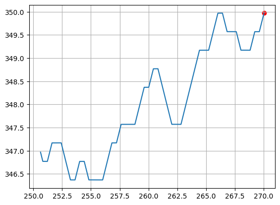
- draw()
This visualization function draws this trajectory object using the matplotlib library. The starting point of the trajectory is shown with a small red circle.
Example:
deepMimoData = DeepMimoData("O1_3p5B", baseStationId=3)
carrier = Carrier(startRb=0, numRbs=25, spacing=15)  # Carrier with 25 Resource Blocks, 15 kHz spacing
xyBounds = np.array([[250, 300], [270, 400]])        # [[minX, minY], [maxX, maxY]]
trajLen = 100
segLen = 2
traj = deepMimoData.getRandomTrajectory(xyBounds, segLen, carrier.curBwp, trajLen, trajDir="-X")
traj.draw()
- print(indent=0, title='Trajectory Properties:', getStr=False)
Prints the properties of this class.
- Parameters:
indent (int) – Used internally to adjust the indentation of the printed info.
title (str) – The title used for the information. By default the text “Trajectory Properties:” is used.
getStr (boolean) – If this is True, the function returns a text string instead of printing the info. Otherwise when this is False (default) the function prints the information.
- Returns:
If “getStr” is true, this function returns a text string containing the information about the properties of this class. Otherwise, nothing is returned (default).
- Return type:
str or None
- printDiscontinuities()
This method prints all the discontinuities in this trajectory. A discontinuity is a situation where two consecutive points on the trajectory have different sets of paths.
- class neoradium.trjchan.TrjChannel(bwp, trajectory, **kwargs)
This class implements a trajectory-based channel model that can generate spatially and temporally consistent sequences of channel information. It creates channel instances based on the movement of users along a
Trajectory. TheTrjChannelclass has been implemented based on 3GPP TR 38.901 Section 8 with the following additional assumptions:We assume only one frequency bin (\(K_B=1\)) and derive the path power \(P_{l_{RT}}^{RT,real}\) from the multipath information for each path. As explained in “Step 2” of 3GPP TR 38.901 Section 8.4, this implies that the bandwidth \(B\) must be lower than \(c/D\) Hz, where \(c\) is the speed of light and \(D\) is the maximum antenna aperture in either azimuth or elevation.
We skip Steps 4 to 10 in 3GPP TR 38.901 Section 8.4. In essence, we refrain from generating random clusters and rays and only use the deterministic paths calculated through ray-tracing. Consequently, the number of paths is equivalent to the number of clusters, and each cluster contains a single ray.
We use the same Cross-Polarization Ratio (XPR) for all paths. This value (\(\kappa^{RT}\)) is derived from the
xPolPowerparameter (\(X\)) using:
\[\kappa^{RT} = 10^{\frac X {10}}\]For the initial phase values used to calculate the cross-polarization matrix, we opt for the phase values obtained from ray-tracing instead of generating random values (as outlined in “Step 12” of 3GPP TR 38.901 Section 8.4). Additionally, we employ the same phase value for all four initial phase angles: \(\Phi^{\theta \theta}\), \(\Phi^{\theta \phi}\), \(\Phi^{\phi \theta}\), and \(\Phi^{\phi \phi}\). This approach is expected to enhance spatial consistency when generating sequences of channels, which is the main goal of this channel model.
All API functions used in most typical use cases are explained in the documentation of
ChannelModelclass.The typical use case involves creating a trajectory (using
interactiveTrajPoints()andtrajectoryFromPoints(), orgetRandomTrajectory()), using it to obtain aTrjChannelobject, and then calling functions such asgetChannelMatrix(),applyToSignal(),applyToGrid().Please refer to the notebook Using the Trajectory-based Channel Model for an example of using this class.
- Parameters:
bwp (
BandwidthPart) – The bandwidth part object used by the channel model to construct channel matrices.trajectory (
Trajectory) – The trajectory along which the channels are created by this channel model. This object contains multipath information that is used to create sequences of channels.kwargs (dict) –
Here’s a list of additional optional parameters that can be used to further customize this channel model:
- normalizeGains:
If the default value of True is used, the path gains are normalized before being applied to the signals.
- normalizeOutput:
If the default value of True is used, the gains are normalized based on the number of receive antennas.
- normalizeDelays:
If the default value of True is used, the delays are normalized as specified in “Step 3” of 3GPP TR 38.901 section 8.4. Otherwise, the original delays obtained from ray-tracing are used.
- interpolateSlots:
If the default value of True is used, the multipath information for each slot is interpolated to derive multipath information per time symbol. Otherwise, the same multipath information is used for all symbols in the slot, which is faster but less accurate.
- filterLen:
The length of the channel filter. The default is 16 sample.
- delayQuantSize:
The size of delay fraction quantization for the channel filter. The default is 64.
- stopBandAtten:
The Stop-band attenuation value (in dB) used by the channel filter. The default is 80dB.
- txAntenna:
The transmitter antenna, which is an instance of
AntennaElement,AntennaPanel, orAntennaArrayclass. If not specified, a single antenna element is automatically created by default.- rxAntenna:
The receiver antenna, which is an instance of
AntennaElement,AntennaPanel, orAntennaArrayclass. If not specified, a single antenna element is automatically created by default.- txOrientation:
The orientation of transmitter antenna. This is a list of 3 angle values in degrees for the bearing angle \(\alpha\), downtilt angle \(\beta\), and slant angle \(\gamma\). The default is [0,0,0]. Please refer to 3GPP TR 38.901 Section 7.1.3 for more information.
- rxOrientation:
The orientation of receiver antenna. This is a list of 3 angle values in degrees for the bearing angle \(\alpha\), downtilt angle \(\beta\), and slant angle \(\gamma\). The default is [0,0,0]. Please refer to 3GPP TR 38.901 Section 7.1.3 for more information.
- xPolPower:
The Cross-Polarization Power in dB. The default is 10db. It is defined as \(X=10 log_{10} \kappa^{RT}\) where \(\kappa^{RT}\) is the Cross-Polarization Ratio (XPR). In current implementation this value is used for all paths.
Other Properties:
- nrNt:
A tuple of the form
(nr,nt), wherenrandntare the number receiver and transmitter antenna elements, respectively.- pathPowers:
This read-only property returns the path powers for all paths between the base station and the UE at current position on the current trajectory.
- pathDelays:
This read-only property returns the path delays for all paths between the base station and the UE at current position on the trajectory. If the parameter
normalizeDelaysis True, the delays from the ray-tracing are normalized according to “Step 3” in 3GPP TR 38.901 Section 8.4. Note that the delay normalization (if enabled) is only applied to this property; the redirected properties “delays”, “losDelay”, and “nlosDelays” always keep the original delay values from the ray-tracing.- totalBlockage:
This read-only property returns True if the channel is currently at a total blockage point, indicating that there is no communication path between the transmitter and receiver.
TrjPoint Redirection:
The properties phases, delays, powers, aoas, zoas, aods, zods, bounces, losPhase, losDelay, losPower, losAoa, losZoa, losAod, losZod, nlosPhases, nlosDelays, nlosPowers, nlosAoas, nlosZoas, nlosAods, nlosZods, hasLos, numPaths*, and numNlosPaths are redirected to the corresponding property in the
TrjPointclass for the current point (cur) in the trajectory. For examplechannel.losZodis equivalent tochannel.trajectory.cur.losZod.- restart(restartRanGen=False, applyToBwp=True)
This method first resets the current trajectory to its starting position and then calls the base class
restart().- Parameters:
restartRanGen (Boolean) – Ignored for the
TrjChannelclass as it uses deterministic information only.applyToBwp (Boolean) – If set to True (the default), this function restarts the Bandwidth Part associated with this channel model. Otherwise, the Bandwidth Part’s state remains unchanged.
- goNext(applyToBwp=True)
This method is called after each application of the channel to a signal. It updates the timing information of the trajectory and the channel model preparing it for the next application to the input signal. It is assumed that the channel is applied to a single slot of the signal at each application (either in the time or frequency domain).
- Parameters:
applyToBwp (Boolean) – If set to True (the default), this function advances the timing state of the Bandwidth Part associated with this channel model. Otherwise, the Bandwidth Part’s state remains unchanged.
- print(indent=0, title=None, getStr=False)
Prints the properties of this channel model object.
- Parameters:
indent (int) – The number of indentation characters.
title (str or None) – If specified, it is used as a title for the printed information. If None (default), the text “TrjChannel Properties:” is used for the title.
getStr (Boolean) – If True, returns a text string instead of printing it.
- Returns:
If the
getStrparameter is True, then this function returns the information in a text string. Otherwise, nothing is returned.- Return type:
None or str
- getPathGains()
Calculates the gains for Line-of-Sight (LOS) and Non-Line-of-Sight (NLOS) paths separately and combines the results before returning the gains between every RX/TX antenna pair, for every path, at every time symbol.
- Returns:
This function returns a 4-D complex tensor of shape
Ns x Nr x Nt x Np, whereNsrepresents the number of time symbols,NrandNtindicate the number of receiver and transmitter antennas respectively, andNpdenotes the number of paths between the base station and the UE at its current location along its trajectory. If the UE is at a total blockage point, this function returns None.- Return type:
NumPy array or None
- getChanSeqGen(seqPeriod=1, seqLen=10, maxNumSeq=inf, chanCallback=None, seqCallback=None)
This function returns an iterable object that generates sequences of channel matrices based on the given parameters.
Refer to the notebook Creating temporally and spatially consistent sequences of channel matrices for an example of using this method.
- Parameters:
seqPeriod (int) – The sampling period of channel matrices along the trajectory. The default value of
1means all channel matrices are included in the sequence. For instance, if this is set to3, every third channel matrix (i.e., one out of every three slots) is included in the sequence.seqLen (int) – The length of the returned sequences. The default is
10.maxNumSeq (int or float) – The maximum number of sequences to generate. By default, it is set to
np.inf, indicating no additional limit on the number of sequences. In this case, channel sequences are generated until the end of the trajectory.chanCallback (function) –
If provided, this function is called when a new channel matrix is generated and before it is added to the sequence. The function may modify the channel and return the modified channel matrix. The function may also return None, which means the current sequence is not valid and should be dropped. In this case, the generator discards the channels collected in the current sequence and starts a new sequence beginning with the next channel matrix according to
seqPeriod. The default is None which disables this channel preprocessing feature. The user-defined function receives the following parameters:- seqNo:
The sequence number, starting at zero and incremented for each sequence.
- elementNo:
The element index within the current sequence.
- channelMatrix:
The current channel matrix. An
L x K x Nr x NtNumPy array whereLrepresents the number of OFDM symbols,Kdenotes the number of subcarriers,Nris the number of receive antennas, andNtindicates the number of transmit antennas.- channel:
This
TrjChannelobject.
seqCallback (function) –
If provided, this function is called when a new sequence of channels is generated and before it is used by the sequence generator. The function may modify the channel sequence and return the modified sequence. The function may also return None, which means the current sequence is not valid and should be dropped. In this case, the generator discards the sequence and initiates a new one, starting with the next channel matrix according to
seqPeriod. The default is None which disables this sequence preprocessing feature. The user-defined function receives the following parameters:- seqNo:
The sequence number, starting at zero and incremented for each sequence.
- channelSequence:
The sequence of channel matrices. An
S x L x K x Nr x NtNumPy array whereSis the sequence length (theseqLenparameter above),Lrepresents the number of OFDM symbols,Kdenotes the number of subcarriers,Nris the number of receive antennas, andNtindicates the number of transmit antennas.- channel:
This
TrjChannelobject.
- Returns:
An iterable object that yields sequences of channel matrices.
- Return type:
ChanSeqGen
The following example creates sequences of effective channel matrixes (which includes the precoding effect) that do not contain any point with total blockage.
from neoradium import Carrier, PDSCH

carrier = Carrier(numRbs=25, spacing=30) # Carrier with 25 RBs, 30KHz subcarrier spacing
channel = TrjChannel(carrier.curBwp, trajectory,
                     txAntenna = AntennaPanel([2,4], polarization="x"),       # 8 TX antenna
                     rxAntenna = AntennaPanel([1,2], polarization="x"))       # 2 RX antenna
pdsch = PDSCH(carrier.curBwp, numLayers=2, nID=carrier.cellId, modulation="16QAM")

def chanCallback(seqNo, elementNo, channelMatrix, channel):
    # Drop the channels with total blockage
    return None if channel.totalBlockage else channelMatrix

def seqCallback(seqNo, channelSeq, channel):
    # Get the precoder matrix based on the first channel in the sequence
    precoder = pdsch.getPrecodingMatrix(channelSeq[0])
    # Now create and return a new sequence containing the effective channels by applying
    # the precoder to all channels in the sequence
    newSeq = np.stack([channel.getEffChannel(chanMat, precoder) for chanMat in channelSeq])
    return newSeq

chanSeqGen = channel.getChanSeqGen(seqPeriod=1, seqLen=5, maxNumSeq=20,
                                   chanCallback=chanCallback, seqCallback=seqCallback)
channelSequences = np.stack([chanSeq for chanSeq in chanSeqGen])
print(channelSequences.shape)   # Prints: (20, 5, 14, 300, 4, 2) for (numSeq, seqLen, L, K, Nr, Nt)